Additive manufacturing equipment combining electron beam selective melting and electron beam cutting

A technology of additive manufacturing and selective melting, which is applied in the field of additive manufacturing and can solve the problems of inability to perform surface processing of inner channels, poor surface finish, and reducing the overall efficiency of parts manufacturing.

Active Publication Date: 2017-06-13
TSINGHUA UNIV
View PDF12 Cites 34 Cited by
  • Summary
  • Abstract
  • Description
  • Claims
  • Application Information

AI Technical Summary

Problems solved by technology

As for the problem of poor surface finish of parts in the electron beam selective melting process, usually in the follow-up process, the surface quality is improved by means of "subtraction", which not only reduces the overall efficiency of part manufacturing, but also has inner pores. Problems such as inability to perform surface processing

Method used


Image

  • Additive manufacturing equipment combining electron beam selective melting and electron beam cutting
  • Additive manufacturing equipment combining electron beam selective melting and electron beam cutting
  • Additive manufacturing equipment combining electron beam selective melting and electron beam cutting

Examples


Embodiment 1

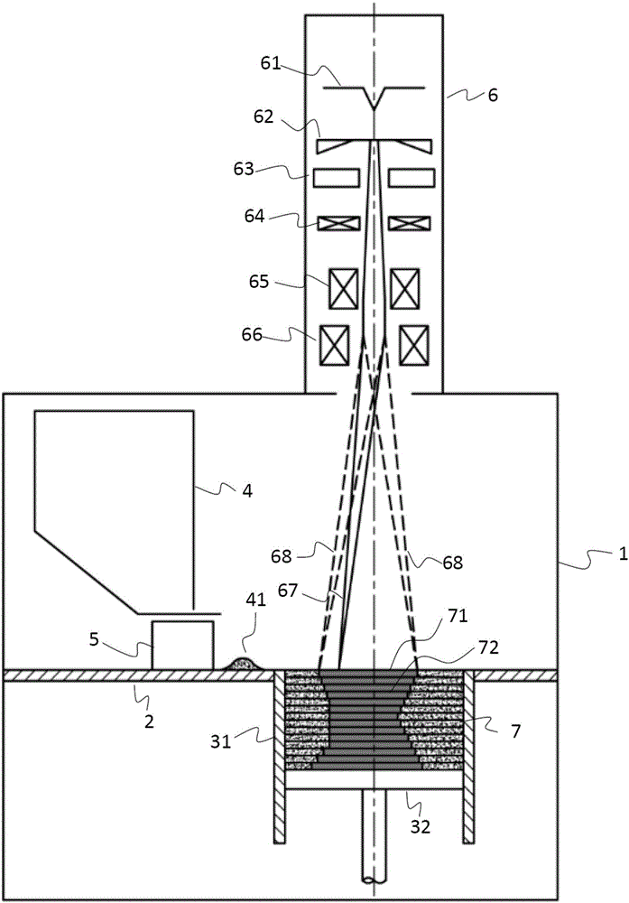
[0075] Such as figure 1 As shown, according to an embodiment of the present invention, the additive manufacturing equipment using electron beam selective melting and cutting composite includes: vacuum forming chamber 1, working platform 2, forming cylinder 31, piston type lifting device 32, powder feeder 4, A powder spreader 5, an electron beam emission focusing scanning device 6 and a control computer as a controller.

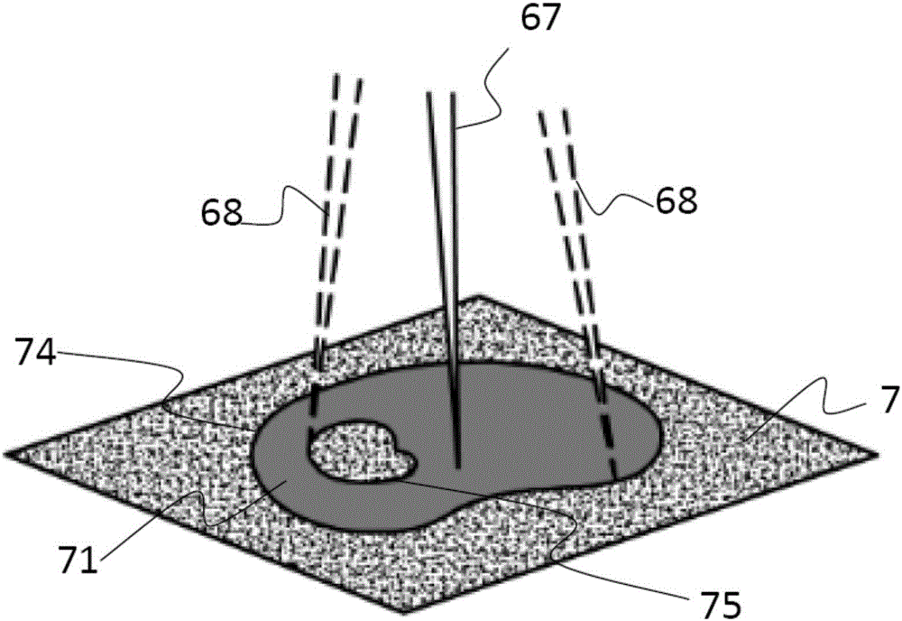
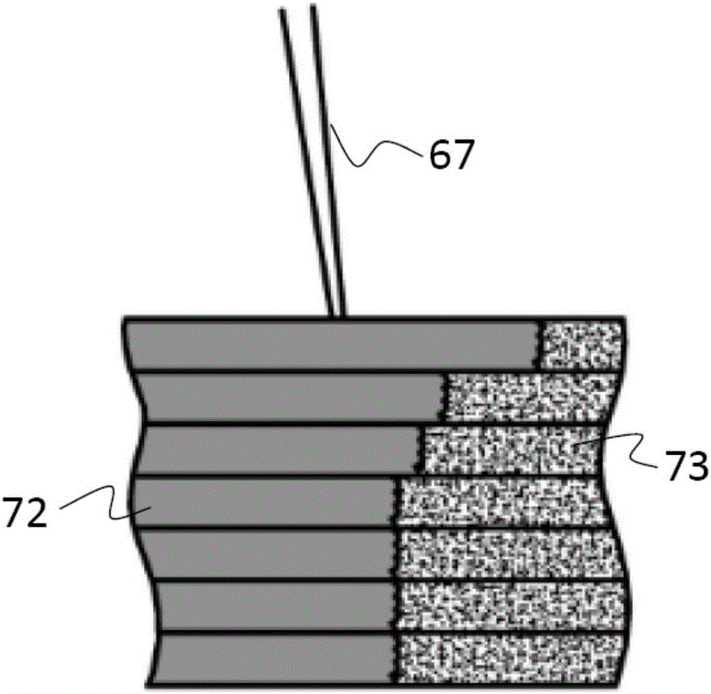
[0076] The electron beam emitting and gathering scanning device 6 includes a filament 61 generating an electron beam 67, a cathode 62, a grid 63, an anode 64, a focusing coil 65, and a deflection coil 66, which generate an electron beam 67 for scanning the forming area, heating, sintering and melting the powder , Cut the inner and outer contours of the formed material.

[0077] The vacuum forming chamber 1 provides a vacuum environment for the selective melting process, and a working platform 2 is arranged horizontally in the middle.

[0078] The powder feed...

Embodiment 2

[0090] Figure 8 with Figure 9 Shown are additive manufacturing equipment using electron beam selective melting and cutting according to other embodiments of the present invention, including multiple electron beam emission focusing scanning devices 6 for selective melting and cutting additive manufacturing equipment. Other compositions are similar to that of Example 1, and its process is also similar to that of Example 1, which will not be repeated here.

[0091] in, Figure 8 It shows the combination of two electron beam emitting and focusing scanning devices 6, the electron beams emitted by the two electron beam emitting and focusing scanning devices 6 all have three different working modes of heating, melting deposition and electron beam cutting, and the two electron beams The scanning areas of the beam emitting focusing scanning device 6 overlap only at the edge, and more than 90% of the scanning areas do not overlap each other. Two electron beam emitting and gathering...


PUM


Abstract

The invention discloses additive manufacturing equipment combining electron beam selective melting and electron beam cutting. The additive manufacturing equipment is characterized in that a same electron beam transmitting, clustering and scanning device can transmit electron beams in three modes, namely heating, selective melting and electron beam cutting. The electron beams in the heating mode are transmitted, so that scanning preheating is conducted on a powder bed; the electron beams in the selective melting mode are transmitted, so that scanning melting is conducted on powder in a section contour, and a part section layer in need is formed; and the electron beams in the electron beam cutting mode are transmitted, so that cutting scanning is conducted on the inner contour and the outer contour of a part section for once or multiple times, rough edges and fusion powder on the contours are removed or cut away, and the precise and smooth inner contour and the outer contour of the part section are obtained. The heating process, melting deposition process and contour cutting process are repeated, and a three-dimensional solid part in need is finally obtained. By means of the additive manufacturing equipment combining electron beam selective melting and electron beam cutting, the finish degree of the inner surface and the outer surface and tiny inner hole formation capacity of an electron beam selective melting product can be increased.

Description

technical field [0001] The invention relates to the field of additive manufacturing, in particular to a method of using electron beams to selectively melt and heat materials so that the materials are sintered or melted and deposited layer by layer, and at the same time, electron beams are used to cut the profile of the formed material to separate the formed material from the powder to achieve high performance and high efficiency. Additive manufacturing equipment for efficient and high-precision 3D parts. Background technique [0002] Electron beam selective melting (EBSM) is a typical additive manufacturing process, which has great advantages in three-dimensional forming of complex structures and special materials. The electron beam selective melting process uses a high-energy electron beam as a heat source to sinter or melt powder materials layer by layer, so that the materials are piled up layer by layer. [0003] However, similar to other additive manufacturing processes...

Claims


Application Information

Patent Timeline
Patent Type & Authority Applications(China)
IPC IPC(8): B22F3/105B28B1/00B23K15/08B33Y10/00B33Y30/00
CPCB22F3/003B23K15/08B28B1/001B33Y10/00B33Y30/00B22F10/10B22F10/00B22F10/36B22F12/49B22F10/32B22F10/28B22F10/366B22F12/50B22F12/45Y02P10/25B22F2003/247B33Y40/20B22F3/105B33Y50/02B29C64/141B23K15/0013B23K15/002B23K15/0033B23K15/004B23K15/0086B23K15/06H01J37/04
Inventor 林峰周斌闫文韬李宏新张磊张婷郭超
Owner TSINGHUA UNIV
Why Eureka
Try Eureka