Taper-sleeve Grinding Device for Machining Back-cone Sealing Ring

A technology of sealing ring and inverted cone surface, which is used in grinding workpiece supports, metal processing equipment, grinding/polishing equipment, etc., can solve problems such as difficulty in effectively obtaining sealing rings

Active Publication Date: 2018-08-14
XIHUA UNIV
View PDF4 Cites 0 Cited by
  • Summary
  • Abstract
  • Description
  • Claims
  • Application Information

AI Technical Summary

Problems solved by technology

[0003] Since the cone angle of the conical sealing surface on the sealing ring in the conical mechanical seal is small, the value is generally only a few minutes to tens of ten, so the maximum cutting amount of the end face in the axial direction during processing is only tens of microns, and Due to the very high requirements on the surface quality of the sealing end face, including surface roughness, flatness, perpendicularity to the axis, etc., it is difficult to obtain the sealing ring with a tapered sealing surface effectively by general methods.

Method used


Image

  • Taper-sleeve Grinding Device for Machining Back-cone Sealing Ring
  • Taper-sleeve Grinding Device for Machining Back-cone Sealing Ring
  • Taper-sleeve Grinding Device for Machining Back-cone Sealing Ring

Examples


Embodiment Construction

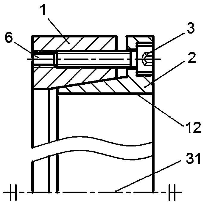
[0021] figure 1 Shown is the basic form of an overall structure of the tapered sleeve grinding device for processing inverted cone sealing rings according to the present invention, including an outer casing structure 1 and an inner insertion structure 2 that can be mated with opposite ends in the axial direction. And can be mutually connected and fastened by connecting structures 3 arranged at equal intervals along the circumference. in:

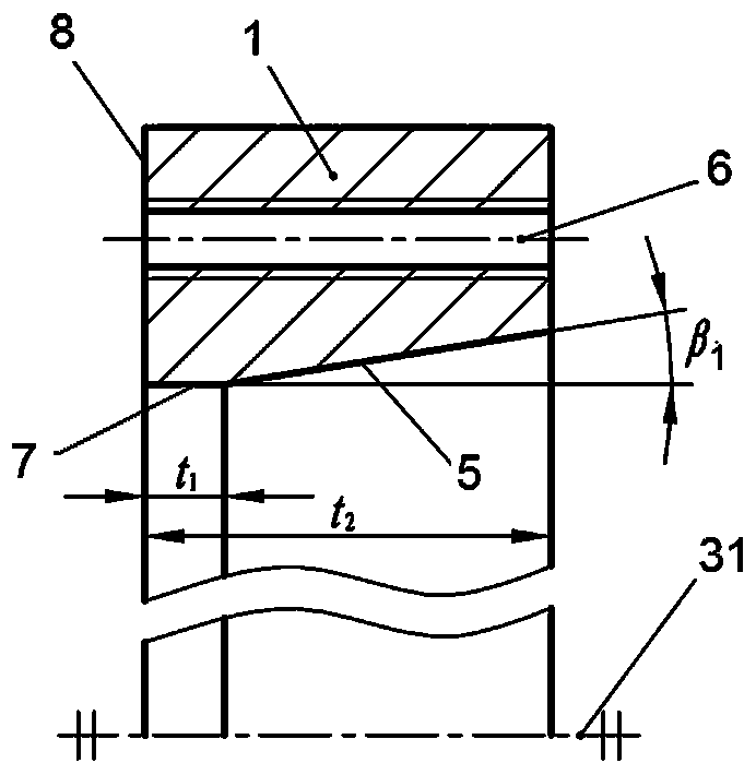
[0022] The outer casing structure 1 is a cylindrical structure, and its radial outer side is provided with 18 threaded through holes or light holes 6 that can be matched with the connection structure 3 such as screws or bolts and nuts at equal intervals along the circumference, for interpolation structure 2 interconnected tightly.

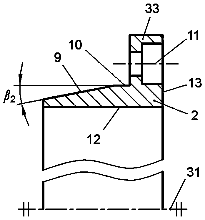
[0023] The socket-fitting parts of the outer casing structure 1 and the insertion structure 2 take the central axis 31 as the center of rotation and have taper angles respectively. β 1 The working surface of ...


PUM


Abstract

The invention discloses a taper sleeve type grinding device for machining an inverted cone sealing ring. The device comprises a group including an outer sleeve structure and an inner insertion structure, wherein the outer sleeve structure and the inner insert structure can be connected and fastened to each other through a connecting structure in a way that the opposite ends of the outer sleeve structure and the inner insert structure are matched in a socket way along the axial direction; the socket matching parts of the outer sleeve structure and the inner insert structure are rotation matching surfaces including an inner concave conical hole surface and an outer convex frustum surface; each rotation matching surface takes a central axis as a rotation center; the inner concave conical hole surface is provided with a taper angle beta 1; the outer convex frustum surface is provided with a taper angle beta 2; the taper angle beta 1 of the rotation surface of the outer sleeve structure is more than or equal to the taper angle beta 2 of the rotation surface of the inner insertion structure; the other end surface, in the backward direction of the socket end, of the outer sleeve structure is a reference surface; an axial internal concave structure of a cylindrical internal hole surface is arranged in the inner insertion structure; the cylindrical internal hole surface also takes an axis as a rotation center; and the internal diameter of the cylindrical internal hole surface is adaptive to the outer diameter of the machined sealing ring. The grinding device can be used to conveniently and accurately machine a sealing surface on a sealing end surface, wherein the taper angle is only about a few minutes or tens of minutes, the maximal cut amount along the axial direction is only tens of micrometers, the requirement on the surface quality of the sealing end surface is very high, and especially the sealing surface has an inverted cone surface.

Description

technical field [0001] The invention relates to a grinding device for machining the sealing end face of a sealing ring, in particular to a sealing ring with an inverted tapered sealing end face. Background technique [0002] The core components to achieve sealing in the mechanical seal are the moving ring which is axially fixed and can rotate with the shaft, and the non-rotating static ring which is arranged opposite to the moving ring through the sealing surface of the shaft end and can be used for axial floating. Cone mechanical seal refers to the sealing surface of the moving ring and / or static ring with a positive or reverse conical sealing surface with a certain taper in the radial direction and the end surface, and the adjustment is made by changing the parameters of the conical surface. The dynamic and static pressure effect of the fluid film formed by the medium between the sealing end faces to obtain sufficient opening force and fluid film rigidity. Cone mechanical...

Claims


Application Information

Patent Timeline
Patent Type & Authority Patents(China)
IPC IPC(8): B24B19/09B24B41/06
CPCB24B19/09B24B41/06
Inventor 王和顺朱维兵张均富杨伟
Owner XIHUA UNIV
Why Eureka
Try Eureka