Intelligent polishing system for machining chair legs

A chair leg and intelligent technology, applied in the field of hardware processing equipment, can solve the problems of affecting the processing quality, reducing the applicability of the wax block locking device, and poor quality stability

Active Publication Date: 2017-06-13
GUANGDONG LXD ROBOTICS CO LTD
View PDF8 Cites 9 Cited by
  • Summary
  • Abstract
  • Description
  • Claims
  • Application Information

AI Technical Summary

Problems solved by technology

Due to the complex structure of the office chair legs, when the robot grabs the office chair legs for processing, the gap control requirements between the fixture and the office chair legs are very high: if the gap between the fixture and the office chair legs is too large, Then the fixture cannot clamp the chair legs of the office chair, so that the chair legs of the office chair will become loose, causing displacement during processing, which will affect the processing quality; Only by aligning with the clamping position can the office chair legs be successfully grasped, which increases the difficulty of control
Moreover, even the legs of office chairs of the same model have certain deformations, and the shape and size cannot be exactly the same. However, the existing clamps for the legs of office chairs cannot be adjusted according to the deformation of the legs of office chairs. The chair feet cannot be aligned with the clamping position of the fixture, and the adaptability of the fixture is poor
[0003] Moreover, due to the various structures of office chair legs, there are a large number of complex curved surfaces, and polishing is difficult. At present, manual polishing is used, which is inefficient, with large differences between individual products and poor quality stability.
Furthermore, the wax block locking device of the existing polishing machine is usually fixedly installed on the waxing machine, and the wax block locking device is fixed and cannot be adjusted, so it can only be used for polishing wax of the same size. When the size of the polishing wax changes , the applicability of the wax block locking device is reduced

Method used


Image

  • Intelligent polishing system for machining chair legs
  • Intelligent polishing system for machining chair legs
  • Intelligent polishing system for machining chair legs

Examples


Embodiment Construction

[0055] The technical solutions of the present invention will be further described below in conjunction with the accompanying drawings and through specific implementation methods.

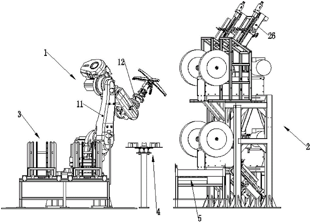
[0056] The intelligent polishing system for processing chair legs of the present embodiment, such as figure 2 As shown, a robot 1 and a polishing machine 2 are included, and the polishing machine 2 is arranged in the working area of ​​the robot 1;

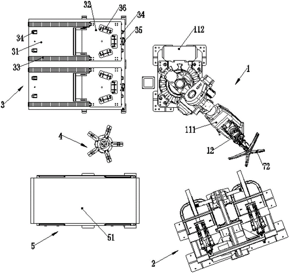
[0057] Described robot 1 comprises robot body 11 and chair foot grasper 12, and described chair foot grabber 12 is installed on the output shaft of robot body 11; Figure 5 , Figure 6 As shown, the chair foot grabber 12 includes a clamping drive cylinder 13, a clamping support rod 17, a chuck 18 and a guide connector 14, and the guide connector 14 includes a support rod guide tube 142, and the clamping The driving cylinder 13 is arranged at one end of the support rod guide pipe 142;

[0058] The clamping support rod 17 is arranged inside the support...


PUM


Abstract

The invention discloses an intelligent polishing system for machining chair legs. The intelligent polishing system comprises a robot and a polishing machine, wherein a chair leg grabber is mounted on an output shaft of a robot body and comprises a clamping driving cylinder, a clamping supporting rod, a clamping head and a guide connector. The intelligent polishing system for machining the chair legs can grab the office chair legs and send the office chair legs to the polishing machine through the robot, so that the chair legs can be polished. The chair leg grabber controls the clamping supporting rod to stretch and retract through the clamping driving cylinder and adjusts the outwards expanding degree of clamping outwards-expanding pieces so as to control the clamping degree of the office chair legs to adapt to the deformation of the office chair legs and reduce influence of gaps on grabbing of the office chair legs, and operation is more convenient and faster.

Description

technical field [0001] The invention relates to the field of hardware processing equipment, in particular to an intelligent polishing system for processing chair legs. Background technique [0002] Office chair legs usually consist of a seat body and multiple supporting feet, such as figure 1 As shown, one end of the supporting leg 72 is connected to the seat body 71 in a radial shape as a whole; the seat body 71 is provided with a seat post mounting hole 711 . Due to the complex structure of the office chair legs, when the robot grabs the office chair legs for processing, the gap control requirements between the fixture and the office chair legs are very high: if the gap between the fixture and the office chair legs is too large, Then the fixture cannot clamp the chair legs of the office chair, so that the chair legs of the office chair will become loose, causing displacement during processing, which will affect the processing quality; Only by aligning with the clamping p...

Claims


Application Information

Patent Timeline
Patent Type & Authority Applications(China)
IPC IPC(8): B24B29/02B24B27/00B24B41/00B24B41/06B24B57/04B25J15/00B25J15/08
CPCB24B27/0023B24B27/0076B24B29/02B24B41/005B24B41/06B24B57/04B25J15/0047B25J15/086
Inventor 袁小云冯耀权罗智文
Owner GUANGDONG LXD ROBOTICS CO LTD
Why Eureka
Try Eureka