Saw web spindle box assembly and mining boulder strip machine

A spindle box and saw blade technology, applied in stone processing tools, stone processing equipment, work accessories, etc., can solve the problems of cumbersome saw blade replacement, affecting the quality of cutting strip stones, inaccurate assembly positioning, etc., to improve work efficiency and Production efficiency, enhance the accuracy of alignment and assembly, and ensure the effect of cutting performance

Active Publication Date: 2017-06-13
QUANZHOU HAIENDE ELECTROMECHANICAL TECH DEV
View PDF9 Cites 5 Cited by
  • Summary
  • Abstract
  • Description
  • Claims
  • Application Information

AI Technical Summary

Problems solved by technology

[0002] Mine strip machine is a kind of machine for strip processing of mine stone. Traditional stone strip processing is processed by ordinary stone sawing machine. Only one piece can be processed and cut each time. The work efficiency is low and the production cost is low.
At present, there are multi-blade stone sawing machines, which are a cantilever structure. Although multiple saw blades can be suspended, due to the unilateral support, the main shaft is easy to deform, and it is prone to instability and equipment damage during work. Multiple sets of saw blades with large sizes cannot be hung, and the practicability is not strong
In order to overcome the above-mentioned defects of the cantilever structure, there is currently a multi-axis combined connection method to overcome the above-mentioned defects of the cantilever type, but it brings problems such as complex structure, inconvenient assembly, cumbersome saw blade replacement, and inaccurate assembly positioning. Ultimately affect the quality of cut stones, affecting work efficiency and production benefits

Method used


Image

  • Saw web spindle box assembly and mining boulder strip machine
  • Saw web spindle box assembly and mining boulder strip machine
  • Saw web spindle box assembly and mining boulder strip machine

Examples


Embodiment Construction

[0077] The present case will be described in further detail below in conjunction with the accompanying drawings and specific embodiments.

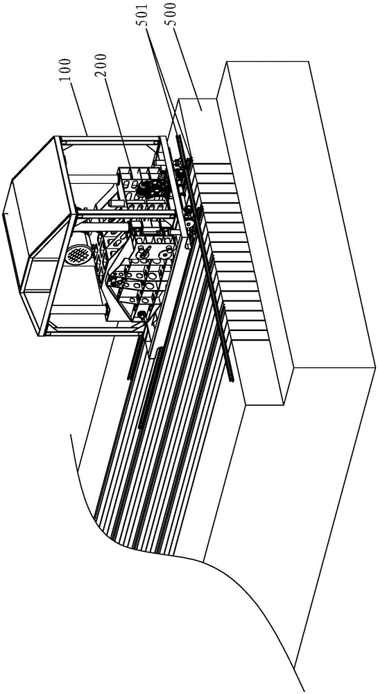
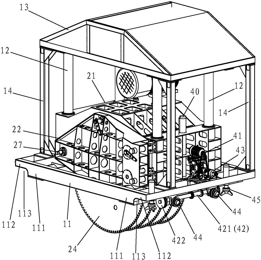
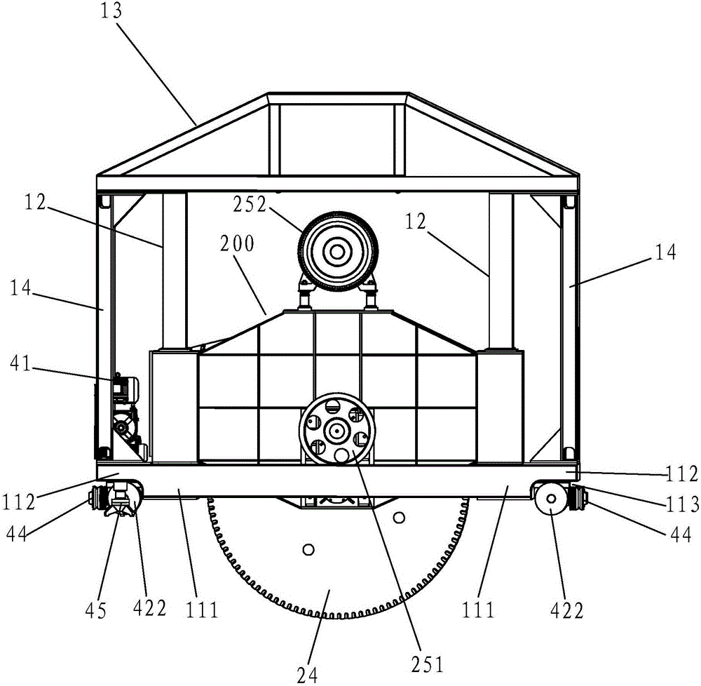
[0078] This case involves a saw blade headstock assembly 200, such as Figure 4 to Figure 7 As shown, it includes a box body 21, a box cover 22 and a main shaft 23. The box cover 22 is movably locked on the box body 21 . In a preferred embodiment, the box cover 22 is movable and installed on the box body 21 in a manner of horizontally shifting and turning relative to the box body 21 . The box body 21 has a box side wall 211 that is arranged opposite to the box cover 22, that is, when the box cover 22 is closed on the box body 21, the box cover 22 and the box side wall 211 are relatively arranged, and the box cover 22 is equivalent to the case. The movable box side wall structure of body 21.

[0079] The main shaft 23 is a shaft structure for carrying saw blades, on which several saw blades 24 are arranged side by side. The main shaft 23...


PUM


Abstract

The invention discloses a saw web spindle box assembly and a mining boulder strip machine. The mining boulder strip machine comprises a rack component and a saw web spindle box assembly, wherein the saw web spindle box assembly comprises a box body, a box cover and a spindle; the box cover is moveably arranged on the box body in a locked manner; the box body has a box side wall arranged opposite to the box cover; a plurality of saw webs are mounted in parallel on the spindle; the spindle extends in a direction perpendicular to the box side wall inside the box body; one end of the spindle is rotationally mounted on the box side wall; a tail base component allowing the other end of the spindle to be moveably inserted and positioned is arranged on the box cover. According to the scheme of the invention, the spindle is smartly mounted on the spindle box which is unique in design, the spindle can be stably and reliably fixed in a mode that two ends are supported, the stability of the saw webs in operation can be ensured, and a plurality of saw webs of any sizes can be arranged on the spindle according to practical demands. Due to design of the moveable box cover, the saw webs can be easily replaced and assembled, properties and practicability of the saw webs can be ensured, the working efficiency can be finally improved, and the production benefits can be increased.

Description

technical field [0001] The invention relates to the field of mine stone processing equipment, in particular to a saw blade spindle box assembly and a mine stone cutting machine. Background technique [0002] Mine strip machine is a kind of machine for strip processing of mine stone. Traditional stone strip processing is processed by ordinary stone sawing machine. Only one piece can be processed and cut each time. The work efficiency is low and the production cost is low. At present, there are multi-blade stone sawing machines, which are a cantilever structure. Although multiple saw blades can be suspended, due to the unilateral support, the main shaft is easy to deform, and it is prone to instability and equipment damage during work. Multiple sets of saw blades with larger sizes cannot be hung, and the practicability is not strong. In order to overcome the above-mentioned defects of the cantilever structure, there is currently a multi-axis combined connection method to over...

Claims


Application Information

Patent Timeline
Patent Type & Authority Applications(China)
IPC IPC(8): B28D1/04B28D7/00B28D7/02
CPCB28D1/044B28D1/048B28D7/00B28D7/02
Inventor 林智敏华新陆
Owner QUANZHOU HAIENDE ELECTROMECHANICAL TECH DEV
Why Eureka
Try Eureka