Two-stage vibration reducing ankle-foot integrated parallel low-impact walking foot mechanism and controlling method
A low-impact, parallel technology, used in motor vehicles, transportation and packaging, etc., can solve problems such as timely and effective absorption, adjustment failure, affecting walking stability, etc., to reduce the control difficulty of the whole machine and suppress low-frequency footing. The effect of shock and improving the stability of the body
- Summary
- Abstract
- Description
- Claims
- Application Information
AI Technical Summary
Problems solved by technology
Method used
Image
Examples
Embodiment 1
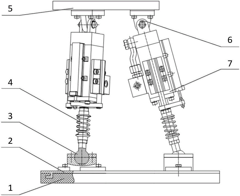
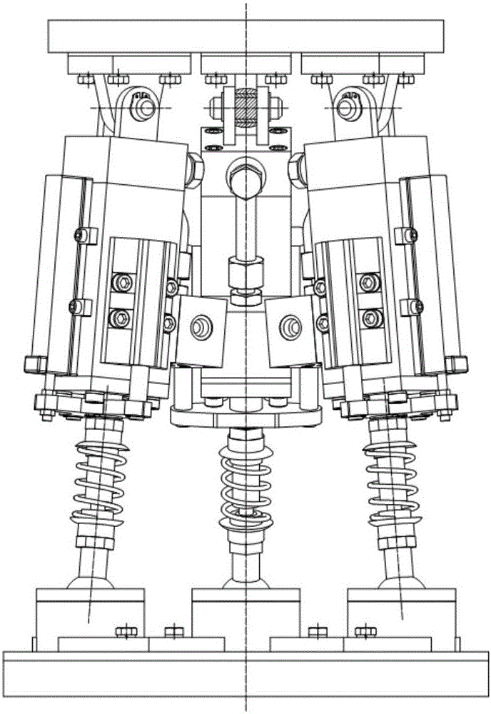
[0032] Such as Figure 1-2 As shown, this embodiment discloses a two-stage shock-absorbing ankle-foot integrated parallel low-impact walking foot mechanism. The walking foot mechanism constitutes the foot end of the robot, including the foot-leg connection platform, the bottom connection platform of the foot end, three sets of moving pairs, three One set of revolving pairs, three sets of ball pairs, the bottom of the foot is connected to the platform to simulate the foot of the robot, and the moving pair is the driving pair, which simulates the leg of the robot.
[0033] The foot bottom connection platform is equipped with a six-dimensional force sensor, and the lower surface of the foot bottom connection platform 2 is inlaid with a friction damping pad 1, which is the first level of vibration reduction. The foot bottom connection platform 2 is connected with three sets of ball pairs 3 The lower ends of the three groups of moving pairs 7 are connected, and the upper ends of ea...
Embodiment 2
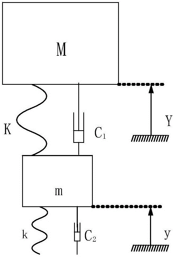
[0035] Such as Figure 3-4 As shown, animals suitable for walking basically have well-evolved feet. With reference to the relevant theoretical knowledge of bionics, a physical model of bionic walking feet was established. On the premise that the walking foot mechanism instantaneously and effectively buffers and avoids the phenomenon of rebounding, the parameters between The relationship is as follows:
[0036]
[0037] M: torso mass, m: walking foot mass, K: leg stiffness, k: parallel walking plantar stiffness, c 1 : leg damping, c 2 : Parallel walking plantar damping, Y: Leg displacement, y: Parallel walking plantar displacement;
[0038] Lumped parameter matching design criteria for parallel walking foot mechanism:
[0039] The condition for avoiding jumpback is: π 2 VKm / 2k>emv, k / K1 / 2, V: the falling speed of the leg, v: the falling speed of the sole;
[0040] The best matching parameters are: mass ratio m / M=0.2, stiffness ratio k / K=4~5, damping ratio c 1 / c 2 =0...
Embodiment 3
[0043] Such as Figure 5 As shown, the design of the walking foot structure starts from the matching with the whole machine, based on the parallel mechanism with few degrees of freedom. A 3-RPS parallel mechanism with few degrees of freedom is developed, which is suitable as a walking foot mechanism. The mechanism has three sets of identical motion branches. A ball pair and a rotating pair are respectively fixed between the foot-leg connection platform and the bottom connection platform of the foot. Secondary connection, the center points of the three groups of motion branches do not coincide in space, and the three groups of motion branches are arranged in a mirror-symmetrical way on the platform, which has better force characteristics. The mechanism can realize two rotational degrees of freedom along the x and y directions and one translational degree of freedom along the z direction.
[0044] The corresponding relationship between the mechanism structure and the mechanical...
PUM
 Abstract
Description
Claims
Application Information
 - R&D
- Intellectual Property
- Life Sciences
- Materials
- Tech Scout
- Unparalleled Data Quality
- Higher Quality Content
- 60% Fewer Hallucinations
Browse by: Latest US Patents, China's latest patents, Technical Efficacy Thesaurus, Application Domain, Technology Topic, Popular Technical Reports.
© 2025 PatSnap. All rights reserved.Legal|Privacy policy|Modern Slavery Act Transparency Statement|Sitemap|About US| Contact US: help@patsnap.com


