Steel wire rope end ring compressing device
A technology of steel wire rope and compactor, applied in the field of compactor, can solve the problems of poor effect, time-consuming and labor-intensive, etc., and achieve the effect of simple structure and easy portability
- Summary
- Abstract
- Description
- Claims
- Application Information
AI Technical Summary
Problems solved by technology
Method used
Image
Examples
Embodiment 1
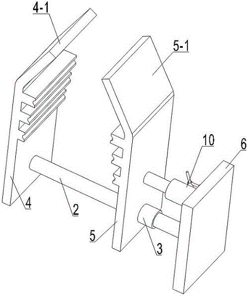
[0028] The wire rope head ring compactor in the present embodiment uses a smooth bar such as an iron rod as the slide rail 2, and the two ends of the slide rail 2 are fixedly connected to the fixed splint 4 and the support plate 6 by welding, and the fixed splint 4, The slide rail 2 and the support plate 6 are fixedly connected together to form the main frame of the compactor. The rail sleeve 3 is a casing whose inner diameter is slightly smaller than that of the slide rail 2 . The movable splint 5 is fixedly connected with the rail sleeve 3, preferably welded together, and the movable splint 5 is driven by the driving device during work, and slides along the slide rail 2 together with the rail sleeve 3.
[0029] The driving device in this embodiment is a jack 9, the bottom end of the jack 9 is fixed on the support plate 6, the telescopic end of the jack 9 is fixedly connected with the movable splint 5, the telescopic direction of the jack 9 is kept parallel to the slide rail ...
Embodiment 2
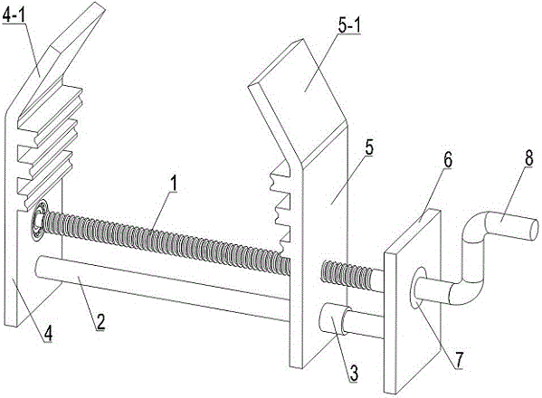
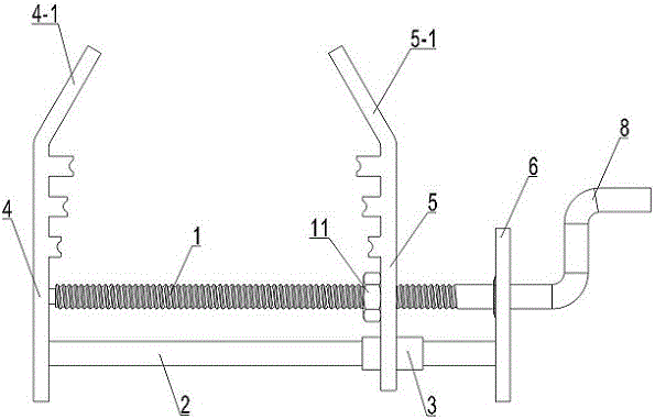
[0036]This embodiment is modified on the basis of Embodiment 1, and the modification lies in the difference of the driving device. The driving device in this embodiment is a driving device in which the screw rod 1 and the nut 11 cooperate, and the specific settings are as follows: the driving device includes a screw rod 1 positioned above the slide rail 2 and arranged parallel to the slide rail 2, and is fixed on the movable splint 5 with the screw rod 1 Nut 11 for cooperating use. The movable splint 5 is provided with a round hole concentric with the center of the nut 11, and the diameter of the round hole is slightly larger than the outer diameter of the nut 11; the screw rod 1 passes through the hole on the movable splint 5 and one end of the nut 11 is connected with the movable splint 5 by the bearing 7, and the screw rod The other end of 1 is provided with a rotary handle 8. Inside the rotary handle 8, the screw 1 is connected to the support plate 6 through the bearing 7,...
PUM
 Abstract
Description
Claims
Application Information
 - R&D
- Intellectual Property
- Life Sciences
- Materials
- Tech Scout
- Unparalleled Data Quality
- Higher Quality Content
- 60% Fewer Hallucinations
Browse by: Latest US Patents, China's latest patents, Technical Efficacy Thesaurus, Application Domain, Technology Topic, Popular Technical Reports.
© 2025 PatSnap. All rights reserved.Legal|Privacy policy|Modern Slavery Act Transparency Statement|Sitemap|About US| Contact US: help@patsnap.com


