A kind of wire rope rope head ring compactor

A technology of a compactor and a steel wire rope, which is applied in the field of compactors, can solve the problems of time-consuming, labor-intensive, and ineffective, and achieve the effect of being easy to carry and having a simple structure.

Active Publication Date: 2019-09-20
STATE GRID CORP OF CHINA +2
View PDF6 Cites 1 Cited by
  • Summary
  • Abstract
  • Description
  • Claims
  • Application Information

AI Technical Summary

Problems solved by technology

Because the ring of the wire rope head ring has a certain rigidity, for a large diameter rope head ring, it is difficult to make the wire rope head ring achieve sufficient deformation by applying force with hands or feet, which is time-consuming and laborious, and the effect is not good

Method used


Image

  • A kind of wire rope rope head ring compactor
  • A kind of wire rope rope head ring compactor
  • A kind of wire rope rope head ring compactor

Examples


Embodiment 1

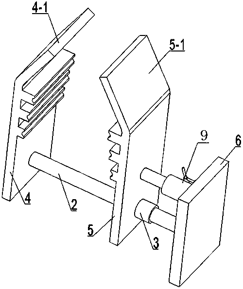
[0028] The wire rope head ring compactor in the present embodiment uses a smooth bar such as an iron rod as the slide rail 2, and the two ends of the slide rail 2 are fixedly connected to the fixed splint 4 and the support plate 6 by welding, and the fixed splint 4, The slide rail 2 and the support plate 6 are fixedly connected together to form the main frame of the compactor. The rail sleeve 3 is a casing whose inner diameter is slightly smaller than that of the slide rail 2 . The movable splint 5 is fixedly connected with the rail sleeve 3, preferably welded together, and the movable splint 5 is driven by the driving device during work, and slides along the slide rail 2 together with the rail sleeve 3.

[0029] The driving device in this embodiment is a jack 9, the bottom end of the jack 9 is fixed on the support plate 6, the telescopic end of the jack 9 is fixedly connected with the movable splint 5, the telescopic direction of the jack 9 is kept parallel to the slide rail ...

Embodiment 2

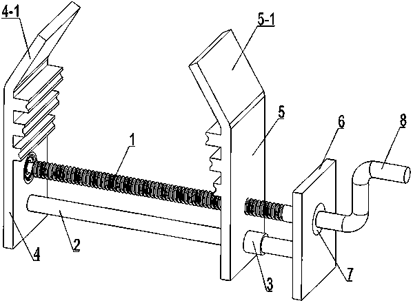
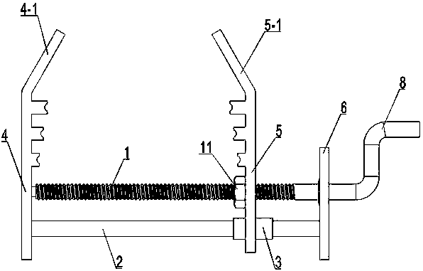
[0036]This embodiment is modified on the basis of Embodiment 1, and the modification lies in the difference of the driving device. The driving device in the present embodiment is the driving device that the screw rod 1 and the nut 11 cooperate, and the specific settings are as follows: the driving device includes a screw rod 1 that is positioned above the slide rail 2 and is parallel to the slide rail 2, and is fixed on the movable splint 5 with the screw rod 1 Nut 11 for cooperating use. The movable splint 5 is provided with a round hole concentric with the center of the nut 11, and the diameter of the round hole is slightly larger than the outer diameter of the nut 11; the screw rod 1 passes through the hole on the movable splint 5 and one end of the nut 11 is connected with the movable splint 5 by the bearing 7, and the screw rod The other end of 1 is provided with a rotary handle 8. Inside the rotary handle 8, the screw rod 1 is connected to the support plate 6 through the...


PUM


Abstract

The invention discloses a steel wire rope end ring compressing device, and belongs to the technical field of compressing devices. The compressing device comprises a sliding rail, and a fixed clamping plate and a supporting plate which are fixed to the two ends of the sliding rail. The sliding rail is sleeved with a rail sleeve. The lower end of a movable clamping plate is fixedly connected with the rail sleeve. The movable clamping plate is driven by a driving device to slide along the slide rail together with the rail sleeve. The compressing device is simple in structure, convenient to carry, capable of adapting to any construction site, capable of flattening a steel wire rope end ring with the large diameter, convenient to use and capable of saving time and labor. The bent portions of the movable clamping plate and the fixed clamping plate are matched with protrusion portions, so that steel wire rope end rings with different diameters can be compressed. The steel wire rope end rings obtained after being flattened by the compressing device can smoothly pass through a pulley or a U-shaped ring or other positions.

Description

technical field [0001] The invention relates to a compactor for a steel wire rope head ring, which belongs to the technical field of compactors. Background technique [0002] In the construction of electric power engineering, with the increase of large-scale construction projects, the lifting capacity is also increasing, resulting in the increasing diameter of the wire rope used in the lifting process. For example, in the transmission line, the transmission voltage level is getting higher and higher, and now it has reached 800kV and 1000kV, and the diameter of the steel wire rope for construction is also getting larger and larger. During construction, the rope head loops of the newly purchased steel wire ropes need to pass through certain gaps (such as pulleys or U-shaped rings, etc.), but due to the large size of the rope head loops, there are certain difficulties in passing through these gaps, so when passing through In front of these gaps, the steel wire rope head rings ...

Claims


Application Information

Patent Timeline
Patent Type & Authority Patents(China)
IPC IPC(8): D07B7/16B21D53/16
Inventor 阎萌董树森董桂西张景辉周雪涛
Owner STATE GRID CORP OF CHINA
Why Eureka
Try Eureka