Electric pull lock of automobile tail door

A tailgate and electric technology, which is applied in electric locks, vehicle locks, building locks, etc., can solve the problems of loose tailgate closing, large cable deformation, and loud noise, and achieve high transmission efficiency, long service life, and small size Effect

Inactive Publication Date: 2017-06-13
DONGYANG GANTE ELECTRICAL CO LTD
View PDF7 Cites 10 Cited by
  • Summary
  • Abstract
  • Description
  • Claims
  • Application Information

AI Technical Summary

Problems solved by technology

[0003] But the existing tailgate lock has the following problems: the driving mechanism of the existing tailgate lock requires a large assembly space, and the space for installing the tailgate lock in automobiles is limited. Door locks cannot be used universally; the tailgate lock's pull wire is usually a steel wire. If the distance between the tailgate lock's driving mechanism and the buckle is too long, the pull wire will be deformed and the pull wire will be pulled longer. Pull the buckle to the specified position, the buckle and the hook will not be hooked tightly, the tailgate lock is not locked, the tailgate will not close tightly, the tailgate will move when the vehicle is driving, the noise is loud and there is a safety hazard; the edge of the tailgate There is a rubber sealing strip on the inner side. The rubber sealing strip has certain elasticity. When the tailgate is closed, the rubber sealing strip collides with the compartment, which will cause the tailgate to have the force to open the tailgate. The elasticity of the rubber sealing strip will offset part of the pull wire to pull the lock. force, so that the lock and the shackle cannot be fastened; when the shackle and the shackle are fastened, the shackle will exert an impact force on the lock instantly, and the movement of the lock by the impact force will bend the cable, which will happen in the long run break the cable

Method used


Image

  • Electric pull lock of automobile tail door
  • Electric pull lock of automobile tail door
  • Electric pull lock of automobile tail door

Examples


Embodiment Construction

[0036] The technical solution of the present invention will be further described below according to the drawings and specific embodiments.

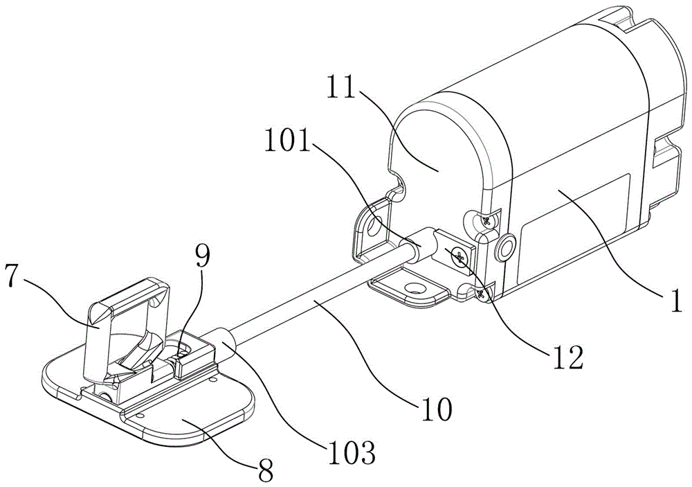
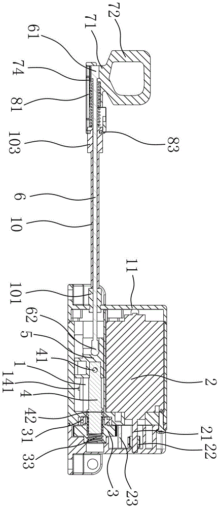
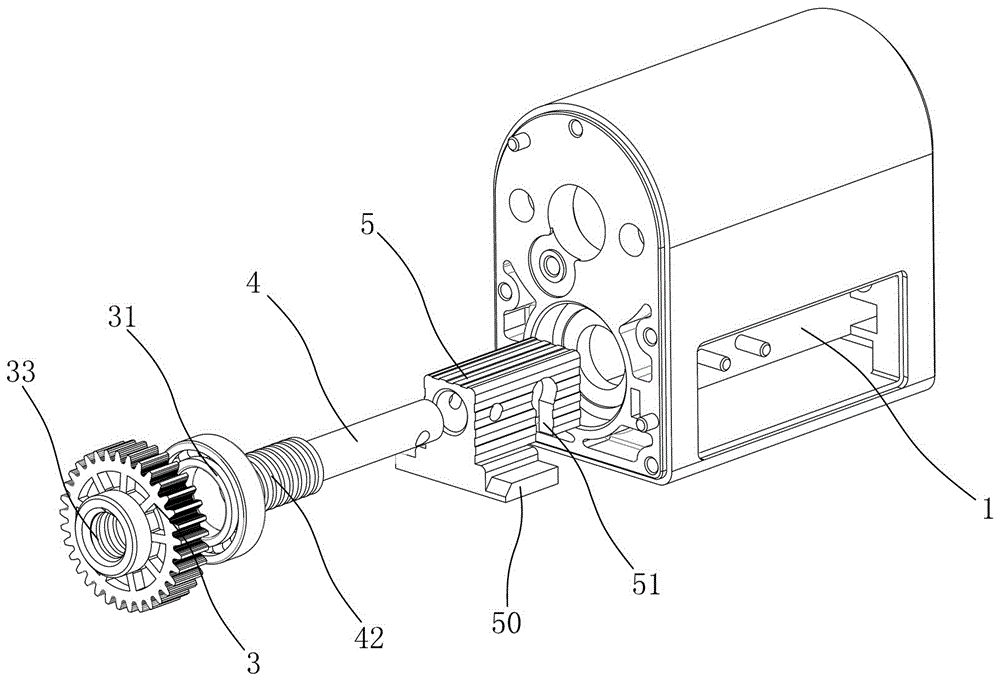
[0037] Depend on figure 1 , figure 2 , image 3 As shown, a kind of automobile tailgate electric zipper of the present invention comprises housing 1, and housing 1 is provided with driving mechanism, and driving mechanism comprises driving motor 2, linkage gear 3, screw mandrel 4 and slide block 5, and driving motor 2 The output shaft 21 is fixed with an output gear 22, the output gear 22 is linked with the linkage gear 3 through the reduction gear, the reduction gear is fixed with the housing or the motor end cover through a rotating shaft 23, the axis of the output gear 22, the axis of the reduction gear and the linkage The axes of the gears 3 are arranged parallel to each other. The interlocking gear 3 is fixed in the housing 1 through the bearing 31, the interlocking gear 3 is formed with a through hole, the outer wall of the scre...


PUM


Abstract

The invention discloses an electric pull lock of an automobile tail door. The electric pull lock comprises a shell, wherein a drive mechanism is arranged in the shell; the drive mechanism comprises a drive motor, a linkage gear, a screw rod and a sliding block; an output gear is fixedly arranged on an output shaft of the drive motor and is linked with the linkage gear; the screw rod is linked with the linkage gear; a guide structure for preventing the sliding block from rotating is formed on the shell, so that the sliding block moves along the axis of the screw rod when the linkage gear rotates; one end, far away from the linkage gear, of the sliding block is fixed to one end of a stay wire and the other end of the stay wire is fixed to a lock catch. The electric pull lock has the advantage of being relatively small in volume and can be suitable for various vehicle models; the tail door of an auto bile employing the electric pull lock can be completely locked, is higher in security, and the tail door does not shake to generate noise. The stay wire of the pull lock is not broken and is longer in service life.

Description

technical field [0001] The invention relates to an electric zipper lock for an automobile tailgate. Background technique [0002] With the rapid development of the automobile industry, people's comprehensive requirements for cars are also gradually increasing. People are no longer satisfied with opening and closing the tailgate lock through the key, and mostly realize this function through the electric control of the electric lock. The existing electric tailgate lock includes a hook-shaped lock hook rotatable at one end and a ring-shaped lock buckle. The hook rotates so that the hook part is located in the buckle, and then the pull wire is pulled by the driving mechanism to move the buckle on the buckle seat, so that the hook and the buckle are hooked together to achieve the purpose of locking the tailgate. [0003] But the existing tailgate lock has the following problems: the driving mechanism of the existing tailgate lock requires a large assembly space, and the space fo...

Claims


Application Information

Patent Timeline
Patent Type & Authority Applications(China)
IPC IPC(8): E05B83/18E05B81/06E05B81/34
CPCE05B81/06E05B81/34E05B83/18
Inventor 蔡桥洪朱炎钊阮刚强王云
Owner DONGYANG GANTE ELECTRICAL CO LTD
Why Eureka
Try Eureka