
Door frame type multi-functional support trolley for tunnel

A gantry-type, multi-functional technology, which is applied in tunnels, tunnel linings, shaft linings, etc., can solve the problems of long single process time, occupying tunnel space, and low arch efficiency, so as to improve competitive advantages, improve safety, The effect of improving installation efficiency

Active Publication Date: 2017-06-13
CHINA RAILWAY ENGINEERING EQUIPMENT GROUP CO LTD
View PDF5 Cites 25 Cited by
  • Summary
  • Abstract
  • Description
  • Claims
  • Application Information

AI Technical Summary

Problems solved by technology

[0004] At present, there are also arch installation auxiliary platforms on the market that can support the excavated section during tunnel construction. However, for extremely weak surrounding rock geology, full-section excavation cannot be used, and only a part of the top can be excavated first. That is, micro-steps, and then immediately use the top section arch support to prevent collapse. The existing arch installation auxiliary platform cannot move forward locally, which meets the requirements for arch installation in this working condition; on the other hand, use the existing The auxiliary platform for the installation of arches needs to assemble the steel arches into a whole on the ground, and then hoist, transport and install the whole, and only one arch can be installed at a time, while drilling and blasting excavation generally requires the installation of two arches. Frame, the existing auxiliary frame for arch installation can only install one arch and then splicing another arch for installation, the single process time occupied by the auxiliary frame for arch installation is too long, the efficiency of arch installation is low, and in addition Assembling the arch frame on the ground will occupy the tunnel space and affect the access of slag trucks, excavators, loaders, etc.

Method used


Image

  • Door frame type multi-functional support trolley for tunnel
  • Door frame type multi-functional support trolley for tunnel
  • Door frame type multi-functional support trolley for tunnel

Examples


Embodiment 1

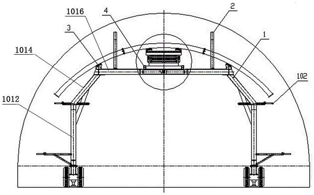
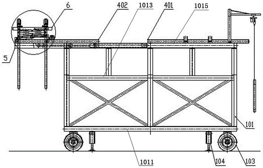
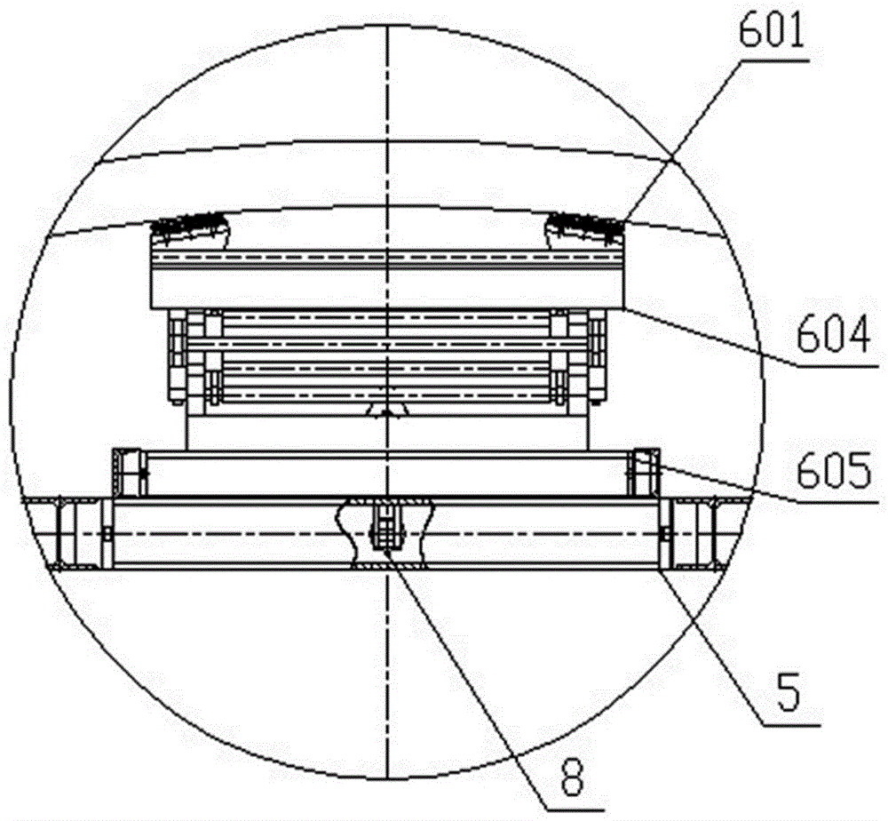
[0024] Embodiment 1: In this embodiment, as Figure 1-4 As shown, a portal frame 101 type multifunctional support trolley for tunnels includes a portal frame 101 assembly 1 and a walking mechanism that drives the portal frame 101 assembly 1 to move back and forth along the tunnel. The portal frame 101 assembly 1 includes The door frame 101 and a number of working platforms 102 symmetrically arranged on the left and right sides of the door frame 101, the top of the door frame 101 is provided with a chute rail 4, and an arch installation device 6 is provided on the chute rail 4, the arch The installation device 6 includes a transport trolley 605 that can move back and forth on the chute rail 4 and a lifting device 604. The lifting device 604 is fixed on the transport trolley 605 below the lifting device 604. Left and right moving mechanisms are provided on the left and right sides of the lifting device 604. And the left and right moving rails for moving the left and right moving ...


PUM


Abstract

The invention discloses a door frame type multi-functional support trolley for a tunnel. The door frame type multi-functional support trolley for the tunnel comprises a door frame and a working platform. The top end of the door frame is provided with a sliding groove track and an arch centering mounting device. The arch centering mounting device comprises a traveling bogie and a lifting device, wherein the traveling bogie is capable of moving backward and forward on the sliding groove track. The lower side of the lifting deviceis fixed to the traveling bogie. The left side and the right side of the lifting device are provided with left-right moving mechanisms and left-right moving tracks for the left-right moving mechanisms to move correspondingly. The left-right moving mechanisms are provided with transportation supports. The sliding groove track comprises a fixed sliding groove track and a movable sliding groove track with the same gauge. The fixed sliding groove track is fixed to the rear of the top end of the door frame and the tail end of the fixed sliding groove track is beyond the tail end of the door frame. The movable sliding groove track is fixed to a sliding platform in the middle of the front of the top end of the door frame. The rear end of the sliding platform is hinged to one end of a sliding cylinder, and the other end of the sliding cylinder is hinged to the door frame. According to the door frame type multi-functional support trolley for the tunnel, the arch centering mounting requirements of a micro-step excavation and support construction method of very weak surrounding rock can be met, and the working procedure time occupied by the arch centering mounting is shortened.

Description

Technical field [0001] The invention relates to the field of tunnel construction support equipment, in particular to a portal type multifunctional support trolley for tunnels. Background technique [0002] The construction method of mountain tunnels in our country is mainly the drilling and blasting method. When the surrounding rock is weak and broken and the self-stability is poor, the steel arch frame must be used for the initial support in time to ensure the construction safety. Due to the backward mechanized construction technology and equipment based on the drilling and blasting method, as well as the low labor cost, the installation of steel arches in tunnel construction in our country mainly uses manual work with loaders or benches. This installation method has many construction personnel, high labor intensity, low work efficiency, poor construction safety, and low installation quality. [0003] With the continuous improvement of high-grade railway construction requirements...

Claims


Application Information

Patent Timeline
Patent Type & Authority Applications(China)
IPC IPC(8): E21D11/40
CPCE21D11/40
Inventor 董恰王洋王占辉张晓晴
Owner CHINA RAILWAY ENGINEERING EQUIPMENT GROUP CO LTD
Learn More