Complex curved surface shape error evaluating method

A technology for complex curved surfaces and surface shape errors, applied to measuring devices, instruments, and optical devices, can solve problems such as cost waste and over-processing, and achieve simple data processing and mathematical operations, short test time, and simple and easy experimental operations line effect

Inactive Publication Date: 2017-06-13
CHANGCHUN INST OF OPTICS FINE MECHANICS & PHYSICS CHINESE ACAD OF SCI
View PDF0 Cites 8 Cited by
  • Summary
  • Abstract
  • Description
  • Claims
  • Application Information

AI Technical Summary

Problems solved by technology

The consequence of this problem is that optical manufacturing is produced according to some traditional indicators, and the obtained optical components are not necessarily the best imag

Method used


Image

  • Complex curved surface shape error evaluating method
  • Complex curved surface shape error evaluating method
  • Complex curved surface shape error evaluating method

Examples


Embodiment Construction

[0030] The present invention will be described in detail below with reference to the accompanying drawings and examples.

[0031] The present invention provides a complex surface shape error evaluation method, which specifically includes the following steps:

[0032] Step 1. Perform interference detection on complex surfaces to obtain surface shape data;

[0033] Step 2, correcting the projection distortion of the surface data, so that the spatial resolutions in all directions of the surface data are consistent;

[0034] Step 3: Fit the corrected surface shape data with zernike polynomials to obtain low-frequency errors; according to the zernike polynomial coefficient Z i , calculate the low-frequency error evaluation index E L ; Among them, C i Indicates the weight of each coefficient;

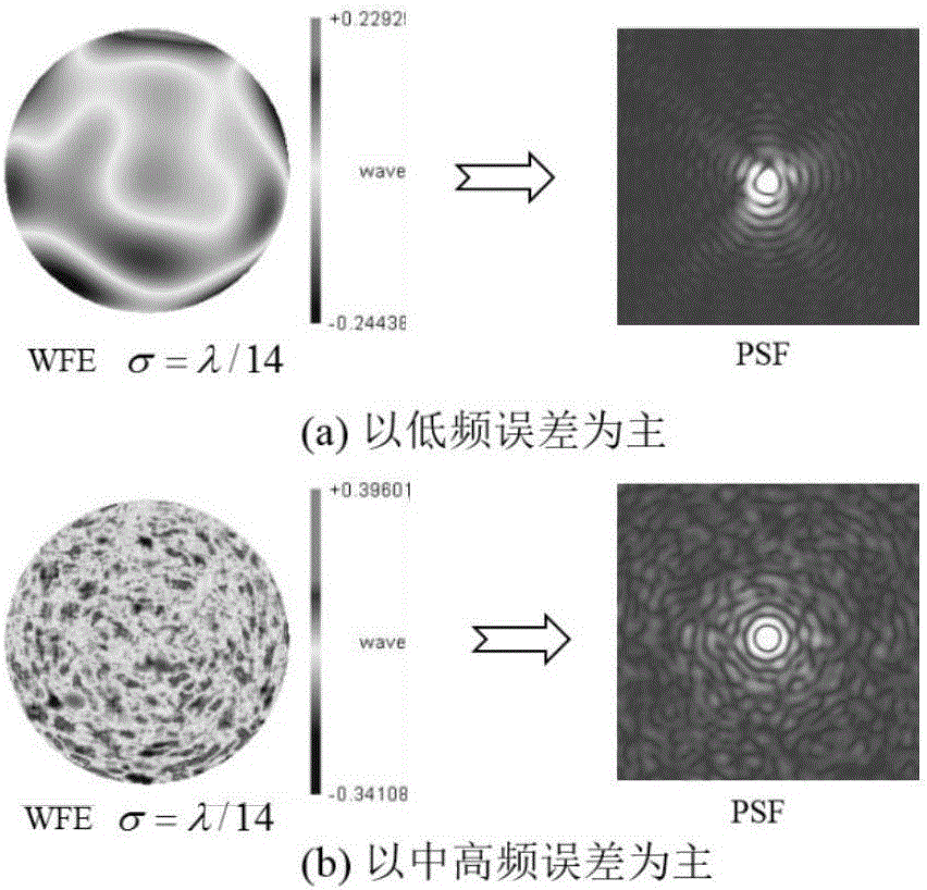
[0035] Based on the analysis of the characteristics of the full-frequency error of the optical surface, we established that the first 37 of the Zernike polynomial represents the low-fre...


PUM


Abstract

The invention discloses a complex curved surface shape error evaluating method. The method comprises performing interference detection on a complex curved surface to obtain surface shape data; secondly correcting the projection distortion of the surface shape data so that the spatial resolutions of the surface shape data in various direction can be consistent; thirdly, performing Zernike polynomial fitting on the corrected surface shape data to obtain low-frequency errors, according to a Zernike polynomial coefficient Zi, computing a low-frequency evaluating index of EL, wherein Ci represents the weight of every coefficient; fourthly, eliminating the low-frequency errors from the surface shape data, and then filtering out high-frequency errors through high-pass filtering to retaining intermediate-frequency errors; fifthly, evaluating the intermediate-frequency errors through a Slope RMS (root-mean-square) index; sixthly, computing the scattering rate of the high-frequency errors to obtain an evaluating index of the high-frequency errors; seventhly, if any of the three indexes above exceeds preset standards, determining that the surface shape errors of the complex curved surface are unqualified. The complex curved surface shape error evaluating method can effectively guide optical manufacturing production from the angle of imaging quality.

Description

technical field [0001] The invention belongs to the technical field of optical system detection and evaluation, and in particular relates to a complex surface shape error evaluation method. Background technique [0002] Aspheric surfaces and free-form surfaces are more and more widely used in optical systems, and the processing accuracy requirements are getting higher and higher. The surface shape requirements of the current high-resolution earth observation system have reached RMS of λ / 60 or even higher . Aspherical surfaces and free-form surfaces will gradually replace spherical surfaces in optical systems. [0003] However, aspheric and free-form surfaces will have manufacturing errors in optical processing, and these errors are parts that deviate from ideal aspheric surfaces. Traditional error characterization methods include error peak-to-valley (PV), root mean square (RMS) and waviness, etc., but these indicators are more or less derived from the concept of tradition...

Claims


Application Information

Patent Timeline
IPC IPC(8): G01B11/24
CPCG01B11/2441
Inventor 张学军曾雪锋薛栋林李锐钢郑立功
Owner CHANGCHUN INST OF OPTICS FINE MECHANICS & PHYSICS CHINESE ACAD OF SCI
Why Eureka
Try Eureka