
Circuit for weakening excitation current peak, electromagnetic flowmeter and electronic device

An excitation current and circuit technology, which is applied in the direction of measuring devices, measuring flow/mass flow, liquid/fluid solid measurement, etc., can solve the problems of excitation circuit damage, reduce the reliability of the excitation circuit, poor stability, etc., and achieve high practicability, The effect of weakening the current peak and low cost

Pending Publication Date: 2017-06-13
CHONGQING CHUANYI AUTOMATION
View PDF9 Cites 0 Cited by
  • Summary
  • Abstract
  • Description
  • Claims
  • Application Information

AI Technical Summary

Problems solved by technology

[0002] The excitation circuit of the electromagnetic flowmeter built with LM317 as the core is an open-loop control system, because there is no negative feedback, so the stability is poor
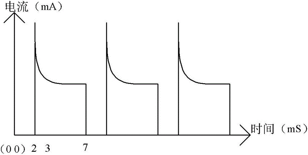
During the experimental test, it was found that in the excitation circuit constant current generator built by LM317, a very large current peak will be generated within 1 ms before each excitation cycle, which will cause certain physical damage to the excitation circuit and reduce the The reliability of the excitation circuit

Method used


Image

  • Circuit for weakening excitation current peak, electromagnetic flowmeter and electronic device
  • Circuit for weakening excitation current peak, electromagnetic flowmeter and electronic device
  • Circuit for weakening excitation current peak, electromagnetic flowmeter and electronic device

Examples


Embodiment 1

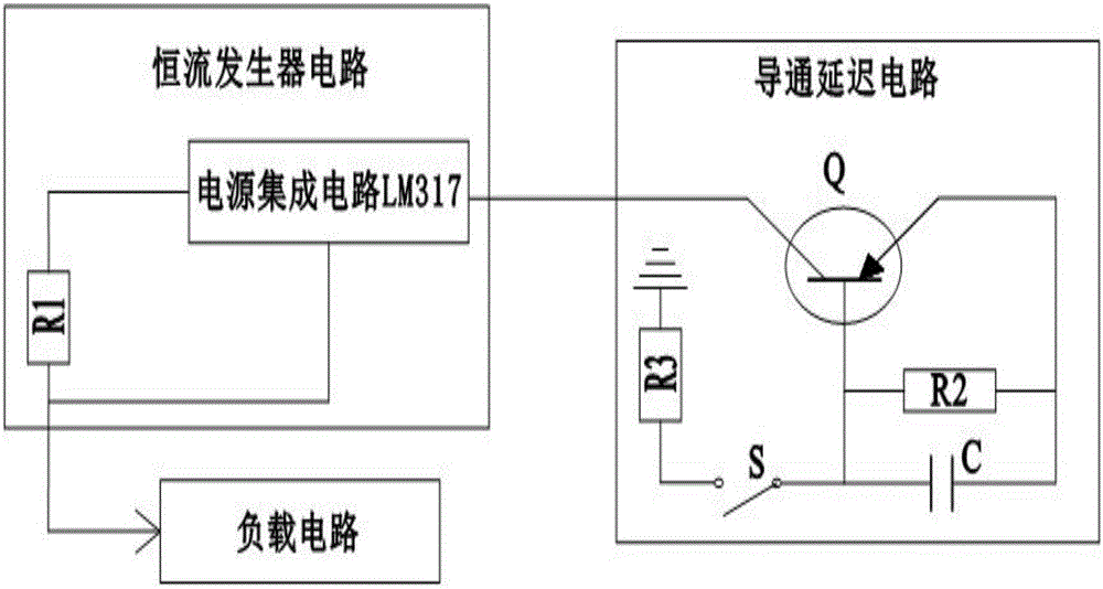
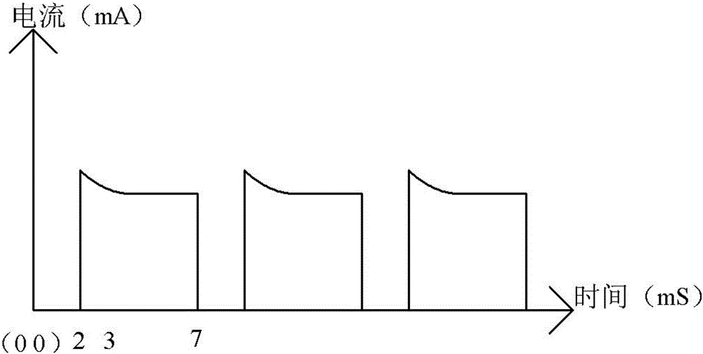
[0027] like Figure 1 to Figure 3 As shown, the circuit for weakening the excitation current spike provided by the present invention includes a constant current generator circuit, a load circuit and a conduction delay circuit. The output end of the constant current generator circuit is electrically connected with the input end of the load circuit, and the The output end of the delay circuit is electrically connected to the input end of the constant current generating circuit.

[0028] As an embodiment, the constant current generator circuit includes a power supply integrated circuit LM317 and a first resistor R1. One end of the first resistor R1 is electrically connected to the voltage output pin of the power supply integrated circuit LM317. The other end is electrically connected with the voltage regulation pin of the power integrated circuit LM317. The two ends of the first resistor R1 of the constant current generator circuit are electrically connected to the voltage outpu...

Embodiment 2

[0036] On the basis of the first embodiment, an electromagnetic flowmeter including the above-mentioned circuit for weakening the excitation current spike is also provided.

Embodiment 3

[0038] On the basis of Embodiment 1 and Embodiment 2, an electronic device including the above electromagnetic flowmeter is also provided.

[0039] Because the present invention adopts the above technical scheme, the technical effect achieved is: the circuit for weakening the excitation current spike, the electromagnetic flowmeter and the electronic device provided by the present invention are composed of a constant current generator circuit, a load circuit and a conduction delay circuit , the functional on-delay circuit is composed of the second resistor R2, the third resistor R3, the capacitor C, the transistor Q and the electronically controlled switch S in a special connection mode, wherein the delay composed of the second resistor R2 and the capacitor C is The circuit controls the conduction degree of the transistor Q within 1ms before the excitation cycle, which well weakens the current spike within the first 1ms of the excitation cycle without affecting the normal excita...


PUM


Abstract

The invention provides a circuit for weakening an excitation current peak, an electromagnetic flowmeter and an electronic device. The circuit comprises a constant-current generator circuit, a loading circuit and a conduction delay circuit, wherein the output end of the constant-current generator circuit is electrically connected with the input end of the loading circuit; the output end of the conduction delay circuit is electrically connected with the input end of the constant-current generator circuit. The circuit for weakening the excitation current peak has the advantages that a delay loop consisting of a second resistor R2 and a capacitor C is used for controlling the conduction degree of a transistor Q in 1ms before an excitation cycle, so that the current peak in 1ms before the excitation cycle is well weakened, and the influence to the normal excitation current after 4ms is avoided; the structure of the whole circuit is simple, the cost is low, the efficiency is high, and the practicality is strong.

Description

technical field [0001] The invention relates to the field of excitation circuits, in particular to a circuit, an electromagnetic flowmeter and an electronic device for weakening excitation current spikes. Background technique [0002] The electromagnetic flowmeter excitation circuit constructed with LM317 as the core is an open-loop control system, which has poor stability due to no negative feedback. During the experimental test, it was found that in the constant current generator of the excitation circuit constructed by LM317, a huge current spike will be generated within 1ms before each excitation cycle, and this current spike will cause certain physical damage to the excitation circuit, reducing the The reliability of the excitation circuit is improved. SUMMARY OF THE INVENTION [0003] In view of the above technical problems, the present invention provides a circuit, an electromagnetic flowmeter and an electronic device for weakening the excitation current peak, whic...

Claims


Application Information

Patent Timeline
IPC IPC(8): G01F1/60
CPCG01F1/60
Inventor 王波周兵
Owner CHONGQING CHUANYI AUTOMATION
Learn More