
Torsion testing device for shaft class

A technology of torsion testing and shafts, applied in measuring devices, force/torque/work measuring instruments, instruments, etc., can solve the problems of affecting the test results, easy to slip, etc., and achieve the effect of good flexibility and high strength

Active Publication Date: 2017-06-13
重庆新锐科技服务有限公司
View PDF6 Cites 3 Cited by
  • Summary
  • Abstract
  • Description
  • Claims
  • Application Information

AI Technical Summary

Problems solved by technology

[0005] The purpose of the present invention is to provide a shaft torque testing device to solve the problem that the torque providing mechanism and the optical axis are easy to slip during the test process and affect the test results

Method used


Image

  • Torsion testing device for shaft class
  • Torsion testing device for shaft class

Examples


Embodiment

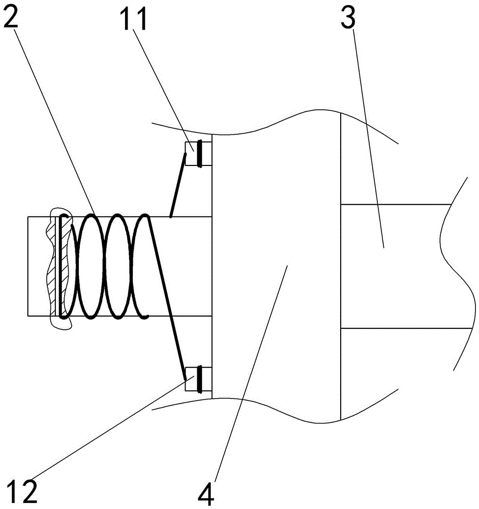
[0018] Embodiment: the axle class torsion test device in this scheme, as figure 2 As shown, it includes a twisted wire 2 made of carbon fiber, a fixed table 7, four strain gauges 5 providing a first driving device 1 and a second driving device 10 providing torque, the first driving device 1 and the second driving device 10 They are located on both sides of the fixed platform 7 respectively. A first support rod and a second support rod are respectively fixed at both ends of the fixed table 7 , a ring-shaped first clamp 6 is mounted on the top of the first support rod, and a ring-shaped second clamp 8 is mounted on the second support rod. Four strain gauges 5 are fixed on the fixed platform 7 and evenly distributed in the circumferential direction of the optical axis 4 . The first disc 3 is installed on the output end of the first driving device 1, and the center of the first disc 3 is integrally formed with a first through hole, and the side of the first disc 3 away from the ...


PUM


Abstract

The invention belongs to the field of devices or methods suitable for a special purpose of measuring force, work, mechanical power or torque and the like produced by impact, and discloses a torque testing device for a shaft class. The device comprises a torsion line made of carbon fibers, a fixing platform, a first driving device for providing torque, and a second driving device for providing the torque, and the first driving device and the second driving device are fixed at the two sides of the fixing platform respectively; the output end of the first driving device is provided with a first round disc, a first through hole is formed in the center of the first round disc, and the first round disc is provided with a first fixing part for fixing the torsion line and a second fixing part for fixing the torsion line; the first fixing part and the second fixing part are symmetric around the diameter of the first round disk. The scheme prevents the situation that a testing result is affected because a torque providing device slips between shafts during a torque testing process.

Description

technical field [0001] The present invention is in the field of devices or methods suitable for special purposes for measuring force, work, mechanical power or torque, eg resulting from impacts. Background technique [0002] The optical axis can be divided into: transmission shaft, which is mainly used to transmit torque without bearing bending moment, such as the long optical axis in the moving mechanism of the crane, the drive shaft of the car, etc. Therefore, the torque detection of the optical axis becomes part of the product inspection. [0003] Carbon fiber (CF for short) is a new type of fiber material with high strength and high modulus fibers with a carbon content of more than 95%. It is a microcrystalline graphite material obtained by stacking organic fibers such as flake graphite microcrystals along the axial direction of the fiber, and undergoing carbonization and graphitization. Carbon fiber is "soft on the outside and rigid on the inside", lighter than metal ...

Claims


Application Information

Patent Timeline
Patent Type & Authority Applications(China)
IPC IPC(8): G01L5/00
CPCG01L5/0061
Inventor 罗贵良
Owner 重庆新锐科技服务有限公司
Learn More