Test platform

A test bench and panel technology, applied in the field of test benches, can solve the problems of various tests of heavy-duty cranes of various tonnages, etc., and achieve the effects of compact structure, easy maintenance, and improved connection strength.

Inactive Publication Date: 2017-06-13
SOUTH CHINA MARINE MACHINERY
View PDF5 Cites 0 Cited by
  • Summary
  • Abstract
  • Description
  • Claims
  • Application Information

AI Technical Summary

Problems solved by technology

[0003] The technical problem to be solved by the present invention is to provide a test bench, which can solve the problems that are not conducive to various tests of heavy cranes of various tonnages

Method used


Image

  • Test platform
  • Test platform

Examples


Embodiment Construction

[0013] The present invention will be described in further detail below in conjunction with accompanying drawing embodiment:

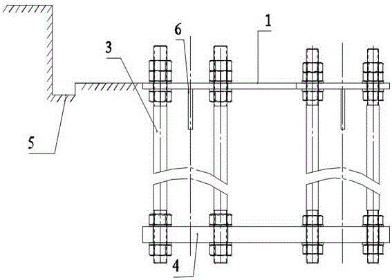
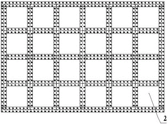
[0014] Such as figure 1 and figure 2 The embodiment shown in the test bench includes an interface panel 1. The interface panel 1 is formed by splicing and welding a plurality of steel plates 2. The lower surface of the interface panel 1 is welded with metal parts 6 at intervals to form a T-shaped frame body. The interface panel 1 is formed by connecting rods 3 It is connected with the straight plate 4 at the bottom to form a panel frame body. The connecting rod 3 is a high-strength stud bolt. The panel frame body is bonded to the foundation 5 through reinforced concrete, and the gap between the panel frame body is filled with reinforced concrete.

[0015] Multiple steel plates are spliced ​​and welded into a panel. After installation, the size span is relatively large. When using it, it is adjusted to the panel that is in contact with it. It can be us...


PUM


Abstract

The invention discloses a test bench, which relates to the technical field of experimental devices, and includes an interface panel, which is formed by splicing a plurality of steel plates, and the interface panel is connected with a straight plate at the bottom through connecting rods to form a panel frame body. Frame bonding. Compared with the prior art, the invention solves the problem that it is unfavorable for heavy cranes of various tonnages to carry out various tests.

Description

technical field [0001] The invention relates to the technical field of experimental devices, in particular to an experimental platform for various tests of heavy cranes of various tonnages. Background technique [0002] The existing test bench includes a plurality of support plates arranged at intervals around the side of the round table, and a test interface panel bonded to the foundation through reinforced concrete is provided under each support plate; since this interface panel is formed independently, the adjustable range is relatively large. It is not conducive to the various tests of heavy cranes of various tonnages. Contents of the invention [0003] The technical problem to be solved by the present invention is to provide a test stand, which can solve the problem that it is unfavorable for heavy cranes of various tonnages to carry out various tests. [0004] In order to solve the above problems, the technical solution adopted in the present invention is: this test...

Claims


Application Information

Patent Timeline
Patent Type & Authority Applications(China)
IPC IPC(8): G01M99/00
CPCG01M99/005
Inventor 李研陈懿王江梁兆环王海江
Owner SOUTH CHINA MARINE MACHINERY
Why Eureka
Try Eureka