
Fast heating-up control method and device based on photo-thermal type and heating furnace

A heating control and fast technology, applied in the direction of temperature control, control/regulation system, non-electric variable control, etc., can solve the problem of abnormal heating time, lack of data analysis and protection measures, lack of database support for temperature control system, affecting the photothermal heating furnace Temperature accuracy and other issues to ensure accuracy, facilitate precise control, and facilitate repair and maintenance.

Active Publication Date: 2017-06-13
HUAZHONG UNIV OF SCI & TECH
View PDF5 Cites 5 Cited by
  • Summary
  • Abstract
  • Description
  • Claims
  • Application Information

AI Technical Summary

Problems solved by technology

[0004] One is to rely on the feedback adjustment mechanism to control the temperature rise. Under the condition of rapid temperature rise and such a high temperature rise rate, it is likely to cause the temperature to exceed the set value and cause production accidents or failure of scientific research experiments;
[0005] The second is that in the photothermal rapid temperature rise device, the temperature of the heated substance is largely related to its own properties. However, the actual temperature measured by the existing device is the indirect temperature of the thermocouple that is not in contact with the sample, which is also to a certain extent It affects the accuracy of the temperature of the photothermal heating furnace;
[0006] The third is that the temperature control system lacks a certain database support, and lacks necessary data analysis and protection measures for possible problems in the system, such as abnormal heating time. Traditional heating units are much larger

Method used


Image

  • Fast heating-up control method and device based on photo-thermal type and heating furnace
  • Fast heating-up control method and device based on photo-thermal type and heating furnace
  • Fast heating-up control method and device based on photo-thermal type and heating furnace

Examples


Embodiment 1

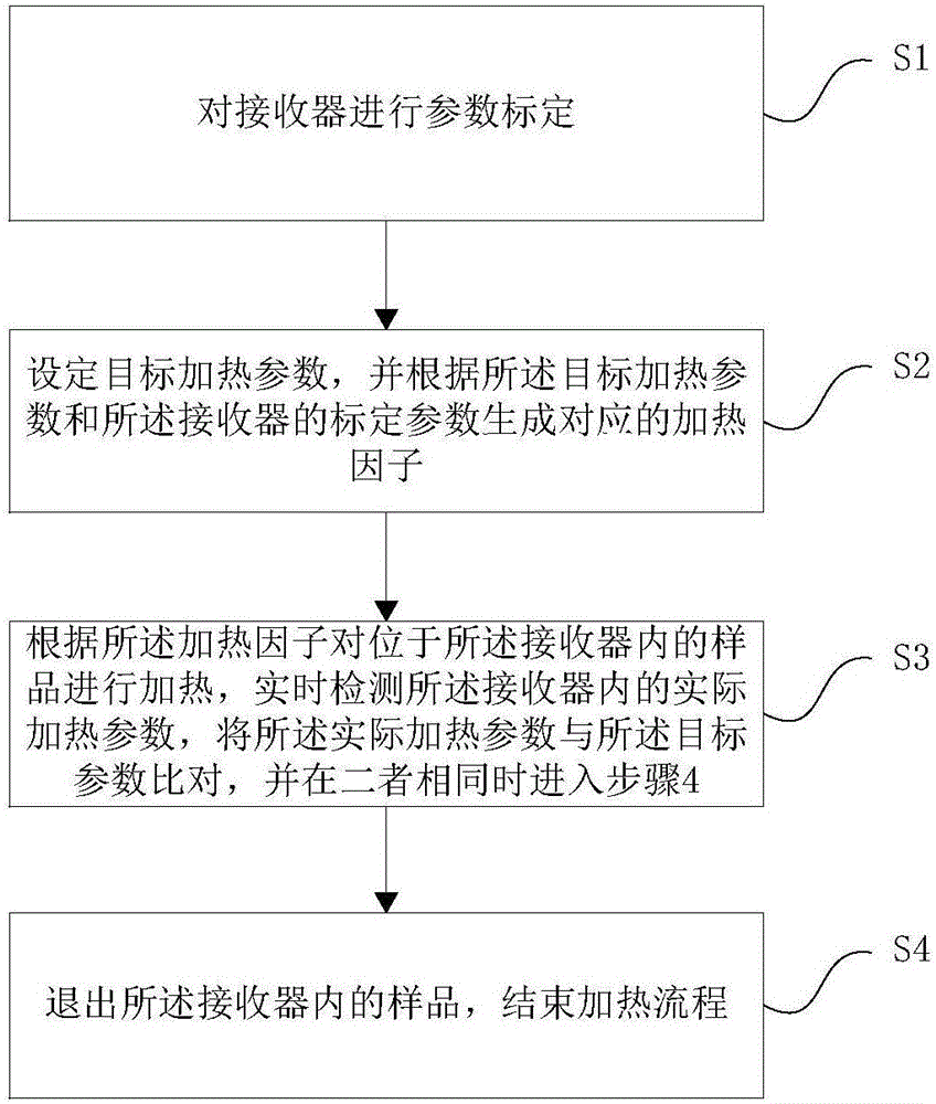
[0056] Embodiment 1. A rapid temperature rise control method based on photothermal type. The following will combine figure 1 A photothermal-based rapid temperature rise control method of the present invention is introduced in detail.

[0057] Such as figure 1 As shown, a rapid temperature rise control method based on photothermal method includes the following steps:

[0058] Step 1: Calibrate the parameters of the receiver where the sample is placed;

[0059] Step 2: setting target heating parameters, and generating corresponding heating factors according to the target heating parameters and calibration parameters of the receiver;

[0060] Step 3: According to the heating factor, the sample located in the receiver is heated by light, the actual heating parameter in the receiver is detected in real time, the actual heating parameter is compared with the target heating parameter, and the If both are the same, go to step 4;

[0061] Step 4: Eject the sample in the receiver t...

Embodiment 2

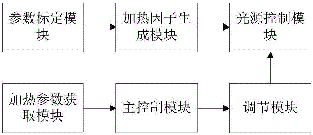
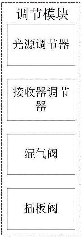
[0079] Embodiment 2. A rapid temperature rise control device based on photothermal type. The following will combine Figures 2 to 5 A photothermal-based rapid temperature rise control device of the present invention is introduced in detail.

[0080] Such as figure 2 As shown, a rapid temperature rise control device based on photothermal type, including:

[0081] The parameter calibration module is used to perform parameter calibration on the receiver where the sample is placed;

[0082] A heating factor generating module, configured to set a target heating parameter, and generate a corresponding heating factor according to the target heating parameter and the calibration parameter of the receiver;

[0083] A light source control module, configured to control the light source to heat the sample in the receiver according to the heating factor;

[0084] A heating parameter acquisition module, used for real-time detection of actual heating parameters in the receiver;

[0085...

Embodiment 3

[0092] Embodiment 3. A fast heating furnace based on photothermal type. A photothermal-based rapid heating furnace of the present invention will be described in detail below.

[0093] A photothermal-based rapid heating furnace includes a light source, a receiver, a data acquisition circuit and the control device.

[0094] The control device generates a corresponding heating factor according to the set target heating parameter and the calibration parameter of the receiver, and controls the light source to heat the sample located in the receiver according to the heating factor; the data The acquisition circuit detects the actual heating parameter in the receiver in real time, and the control device controls the light source to stop heating when the actual heating parameter in the receiver is the same as the target heating parameter, and exits the sample in the receiver.

[0095] In this embodiment, the data acquisition circuit includes one or more of a temperature sensor, an ai...


PUM


Abstract

The present invention relates to a fast heating-up control method and device based on a photo-thermal type and a heating furnace. The method comprises the following steps: performing parameter calibration of a receiver putting samples; setting a target heating parameter, and generating corresponding heating factors according to the target heating parameter and the calibration parameter received by the receiver; performing illumination heating of the samples in the receiver according to the heating factors, detecting an actual heating parameter in the receiver in real time, comparing the actual heating parameter and the target heating parameter, quitting the samples in the receiver when the actual heating parameter is the same as the target heating parameter, and finishing a heating flow. Corresponding heating factors are generated according to the target heating parameter and the calibration parameter of the receiver, active heating of the samples in the receiver are performed according to the corresponding heating factors, and the samples are not directly heated so as to realize fast heating up and ensure accurate control of the heating process.

Description

technical field [0001] The invention relates to the technical field of temperature control, in particular to a photothermal-based rapid temperature rise control method, device and temperature rise furnace. Background technique [0002] Rapid heating furnaces are more and more widely used in current scientific research and production preparation. At present, the mainstream rapid heating furnaces are mainly divided into two types: special resistance wire furnaces and iodine tungsten lamp heating furnaces. The former requires special heating wires. The preparation process is complicated. The requirements for the furnace body are strict. The current heating rate is 180°C-200°C / min, and the cost is relatively high; the latter was first used in metal preparation by the Japan Vacuum Institute of Technology at the end of the 20th century. At present, the heating rate of the domestic iodine-tungsten lamp rapid heating furnace is 600°C-800°C / min, although the heating rate meets the re...

Claims


Application Information

Patent Timeline
Patent Type & Authority Applications(China)
IPC IPC(8): G05D23/20
CPCG05D23/20
Inventor 胡松李寒剑池寰瀛向军苏胜汪一江龙徐凯
Owner HUAZHONG UNIV OF SCI & TECH
Learn More