Demodulation circuit applied to ultrahigh-frequency tag

A demodulation circuit and ultra-high frequency technology, applied in the field of IoT tags, can solve problems such as limited working range, unfavorable envelope demodulation, and inability to realize wave detection functions

Active Publication Date: 2017-06-13
华大恒芯科技有限公司
View PDF4 Cites 2 Cited by
  • Summary
  • Abstract
  • Description
  • Claims
  • Application Information

AI Technical Summary

Problems solved by technology

However, due to the strict requirements of the system on the power consumption area, passive resistors and capacitors need to occupy a large area to ensure that the power consumption of the module is very low, and the simultaneous optimization of area and power consumption cannot be achieved.
In addition, when the diode envelope detection method is adopted, when the signal level at the RF end is close to the diode threshold, the detection function cannot be realized, which is not conducive to envelope demodulation under weak signal conditions, and the working range is limited

Method used


Image

  • Demodulation circuit applied to ultrahigh-frequency tag
  • Demodulation circuit applied to ultrahigh-frequency tag
  • Demodulation circuit applied to ultrahigh-frequency tag

Examples


Embodiment Construction

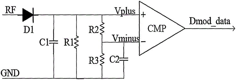
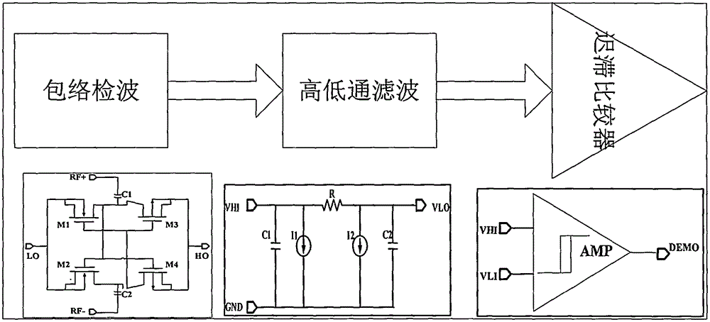
[0015] The new demodulation circuit design focuses on innovations in envelope detection and high and low pass filtering. In order to make the technical means, creative features, goals and effects achieved by the present invention easy to understand, the following focuses on the realization of these two parts of the circuit.

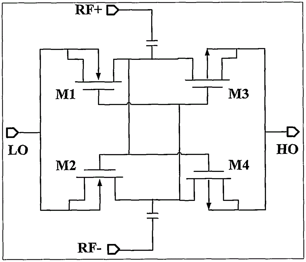
[0016] The structure of the envelope detection module is as follows: image 3 As shown, the gate cross structure is mainly composed of four MOSs M1~M4, the LO terminal is connected to low level (GND), the source and substrate of M1 and M2 are connected to LO, the source and substrate of M3 and M4 are connected to The HO terminal is connected, the drain terminals of the M1 and M3 tubes are connected together and connected to the capacitor C1, and the other end of the capacitor C1 is the RF+ terminal of the input antenna; similarly, the drain terminals of the M2 and M4 tubes are connected together and connected to the capacitor C2, and the capacitor The ot...


PUM


Abstract

The invention discloses a demodulation circuit applied to an ultrahigh-frequency tag. The demodulation circuit comprises a hysteresis comparator, an envelope detection circuit, and a high-low-pass filtering circuit, wherein the input end of the envelope detection circuit is connected with a radio-frequency antenna, the L0 end of the envelope detection circuit is connected with low level, and four low-threshold MOS transistors form a gate crossing structure; envelope detection signals are alternately conducted and output; and the high-low-pass filtering circuit adopts a current source, capacitor and resistor combined structure, a filtering function is realized by use of current sources I1 and I2, capacitors C1 and C2 and a resistor R, and the received envelope detection signals are filtered and transmitted to the hysteresis comparator. By adopting the demodulation circuit, the requirements of the ultrahigh-frequency tag on low power consumption, high performance and small area are met.

Description

technical field [0001] The invention relates to the field of Internet of Things tags, in particular to an application of a demodulation circuit applied to UHF tags. Background technique [0002] In the past ten years, the Internet of Things industry has achieved tremendous development. On the one hand, this is because the Internet and wireless communication make people's lives more convenient, intelligent mobile terminals can maintain information exchange at any time, with high real-time performance, and the demand for the Internet of Things is increasing; on the other hand, with the integration With the rapid development of circuits, there are more and more cheap chips facing ordinary consumer groups, and the applications are more diversified and intelligent. As the most important hardware terminal in the Internet of Things——RFID tags, due to the large demand, wide application, and complex and changeable working environment, the requirements for cost and performance are ve...

Claims


Application Information

Patent Timeline
Patent Type & Authority Applications(China)
IPC IPC(8): G06K19/077
CPCG06K19/07749
Inventor 温立国
Owner 华大恒芯科技有限公司
Why Eureka
Try Eureka