
Peg-clamp co-pressing middle quick energy-saving conducting contact

A technology of conductive joints and conductive heads, applied in conductive connections, clamping/spring connections, circuits, etc., can solve the problems of difficult to disassemble wires, complicated installation, easy to break, etc., to achieve simple and reasonable structure, reduce power loss, and improve conductivity. The effect of efficiency

Inactive Publication Date: 2017-06-13
SHAOGUAN FANGSHENG ELECTRIC EQUIP CO LTD
View PDF0 Cites 1 Cited by
  • Summary
  • Abstract
  • Description
  • Claims
  • Application Information

AI Technical Summary

Problems solved by technology

However, the structure is complicated to install, it is difficult to disassemble the wire after connection, and the wire cannot be put into use again after disassembly (if the terminal conductive lug is used again, it is easy to break)
In addition, because the high-voltage cables are generally bare wires, the length of the hydraulic pliers is relatively long. If the wires are connected under live conditions, the hydraulic pliers are likely to touch other phase wires and cause short-circuit accidents. Therefore, it is not conducive to live work
However, the emergency repair of the power system generally requires live work, otherwise it will have a huge impact on people's lives and industrial production
Therefore, the current intermediate conductive joint is obviously not suitable for use

Method used


Image

  • Peg-clamp co-pressing middle quick energy-saving conducting contact
  • Peg-clamp co-pressing middle quick energy-saving conducting contact

Examples


Embodiment Construction

[0019] The present invention will be further described below in conjunction with accompanying drawing and embodiment:

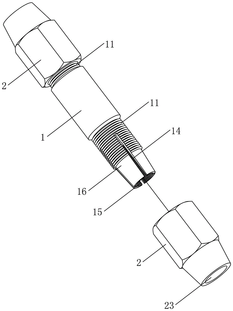
[0020] see figure 1 and figure 2 As shown, a nail clip co-pressing type intermediate fast energy-saving conductive joint includes an intermediate conductive head 1, and the intermediate conductive head 1 is provided with at least two external thread ends 11, and an elastic clip cavity is provided inside the external thread end 11 , the elastic clip cavity is provided with a pointing nail 13 pointing to the axis, and the outer threaded end 11 is connected with an outer lock nut 2, and the outer lock nut 2 is provided with a sleeve hole 23 running through its two ends, and the sleeve hole 23 An extruding tapered surface 21 for radially extruding the elastic clip cavity is provided inside.

[0021] There is one branching spike 13 and it is located in the center of the elastic clip cavity.

[0022] The external threaded end 11 is provided with a concave cavit...


PUM


Abstract

The invention relates to a nail clamp co-pressing type intermediate rapid energy-saving conductive joint, which includes an intermediate conductive head, the intermediate conductive head is provided with at least two external thread ends, and an elastic clip cavity is arranged in the external thread end, and the elastic clip The cavity is provided with an axis-pointing point-point nail, and the outer threaded end of the outer thread is connected with an outer lock nut. The outer lock nut is provided with a sleeve hole running through its two ends, and the sleeve hole is provided with a radial extrusion spring. The extrusion cone of the pocket. The external thread end of this type of nail clip co-pressing type intermediate fast energy-saving conductive connector is provided with an elastic clip cavity and a pointy spike. When the wire is inserted into the elastic clip cavity, the pointy nail is inserted into the gap in the wire and At the same time, when the outer lock nut is tightened, the elastic clip chamber narrows to form an environment conducive to clamping the wire. Its structure is simple and reasonable, the clamping effect is good, the conductivity efficiency is improved, and the power loss is reduced.

Description

technical field [0001] The invention relates to an intermediate conductive joint for electric conductive connection, in particular to a nail clamp co-pressing type intermediate fast energy-saving conductive joint. Background technique [0002] The current intermediate conductive joint for electric conductive connection includes an intermediate conductive head, and the two ends of the intermediate conductive head are provided with wire clips. , to achieve wire clamping. However, the structure is complicated to install, and it is difficult to disassemble the wire after connection, and the wire cannot be put into use again after disassembly (if the terminal conductive lug is used again, it is easy to break). In addition, because the high-voltage cables are generally bare wires, the length of the hydraulic pliers is relatively long. If the wires are connected under live conditions, the hydraulic pliers are likely to touch other phase wires and cause short-circuit accidents. The...

Claims


Application Information

Patent Timeline
Patent Type & Authority Applications(China)
IPC IPC(8): H01R4/50
CPCH01R4/5025
Inventor 曹孝培湛念军
Owner SHAOGUAN FANGSHENG ELECTRIC EQUIP CO LTD
Learn More