Power output protective circuit and device

A technology for power output and circuit protection, applied in emergency protection circuit devices, circuit devices, emergency protection devices with automatic disconnection, etc., can solve the problems of high maintenance costs, insufficient response to abnormal high current faults, and low reliability.

Active Publication Date: 2017-06-13
ZHEJIANG DAHUA TECH CO LTD
View PDF7 Cites 6 Cited by
  • Summary
  • Abstract
  • Description
  • Claims
  • Application Information

AI Technical Summary

Problems solved by technology

When the series PTC protection mode is adopted, although the PTC has the advantages of high reliability and low maintenance cost, the action response time of its over-current protection is long, and the over-current protection point is not accurate enough.
When using the fuse protection method, the fuse has the advantages of high reliability and short action response time, but it cannot b

Method used


Image

  • Power output protective circuit and device
  • Power output protective circuit and device
  • Power output protective circuit and device

Examples


Embodiment 1

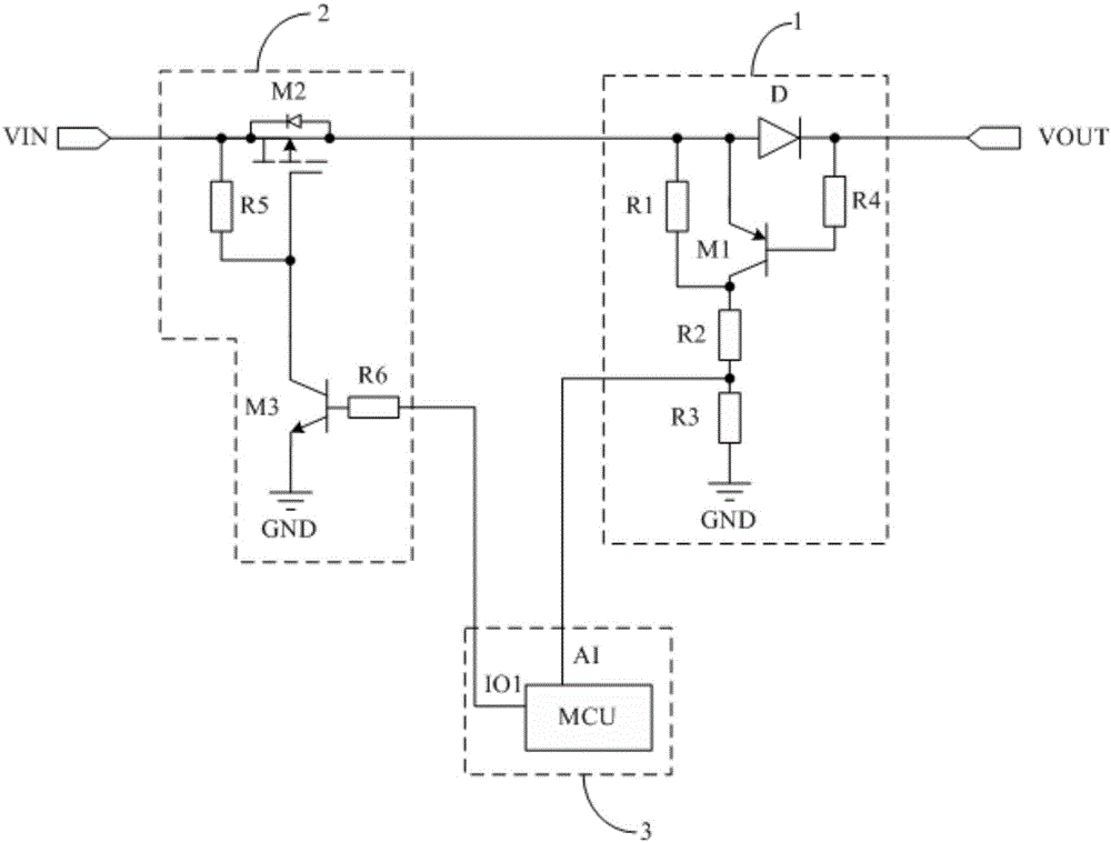
[0133] Such as Figure 3a As shown, the first transistor is a PNP transistor, the second transistor is a P-type MOS transistor, and the third transistor is an NPN transistor.

[0134] (1) When the load connected to the output terminal VOUT of the power supply works normally and is not short-circuited, that is, when the input terminal VIN of the power supply is connected to the output terminal VOUT of the power supply, the diode D has a stable conduction voltage drop, so that the V of the first transistor M1 gs (M1)>V th (M1) is turned on, since the equivalent resistance of the first transistor M1 after turning on is small, it can be ignored. Therefore, the first resistor R1 is short-circuited, and the source of the first transistor M1, the second resistor R2, and the third resistor R3 form a path, so that the voltage V at the second end of the second resistor R2 1 That is, the sampling voltage satisfies the formula: Among them, U 1 is the voltage at the anode of the diode...

Embodiment 2

[0138] Such as Figure 3d As shown, the first transistor is a PNP transistor, the second transistor is a P-type MOS transistor, and the third transistor is an NPN transistor.

[0139] (1) When the load connected to the output terminal VOUT of the power supply works normally and is not short-circuited, that is, when the input terminal VIN of the power supply is connected to the output terminal VOUT of the power supply, the diode D has a stable conduction voltage drop, so that the V of the first transistor M1 gs (M1)>V th (M1) is turned on, since the equivalent resistance of the first transistor M1 after turning on is small, it can be ignored. Therefore, the first resistor R1 is short-circuited, and the source of the first transistor M1, the second resistor R2, and the third resistor R3 form a path, so that the voltage V at the second end of the second resistor R2 1 That is, the sampling voltage satisfies the formula: Among them, U 1 is the voltage at the anode of the diode...


PUM


Abstract

The present invention discloses a power output protective circuit and device. The protective circuit comprises a sampling module, a switch control module and a processing control module. The power voltage received by the sampling module is converted to sampling voltage in proportion, the processing control module confirms load short circuit or overcurrent when determining that the sampling voltage is not larger than a preset overvoltage, sends cut-off control signals to the switch control module and controls the switch control module to stop transmission of received power voltage to the sampling module so as to overcurrent protection. The processing control module sends conduction control signals to the switch control module when determining that the sampling voltage is larger than the preset overvoltage, controls the switch control module to perform continuous conduction to go on transmission of the received power voltage to the sampling module, and performs voltage division of the received power voltage through the sampling module to transmit the voltage to the output end of the power supply so as to supply power to the load. Therefore, the power output protective circuit and device can avoid the problem of damaging of a power supply connected with the input end of the power supply when the load short circuit or overcurrent.

Description

technical field [0001] The invention relates to the technical field of electronic circuits, in particular to a power supply output protection circuit and device. Background technique [0002] In the alarm equipment, it is often necessary to provide a low-voltage DC power supply (generally 12V) to supply power for external equipment such as detectors, sirens, and configuration keyboards. Because the current consumed by these external devices is not large and in order to reduce the design cost, generally the low-voltage DC power supply and the power supply for the alarm device share a power supply. However, when the external equipment is abnormal or artificially damaged, such as short circuit or overcurrent, it may have adverse effects on the low-voltage DC power supply or even the power supply, thereby affecting the normal operation of the alarm equipment, such as abnormal reset, false alarm, etc. [0003] The existing low-voltage DC power supply output protection circuit is...

Claims


Application Information

Patent Timeline
IPC IPC(8): H02H3/087
CPCH02H3/087
Inventor 宋加才
Owner ZHEJIANG DAHUA TECH CO LTD
Why Eureka
Try Eureka