A static synchronous compensator device and control method for a three-phase three-leg distribution network

A technology of static synchronous compensation and power distribution network, applied in circuit devices, reactive power adjustment/elimination/compensation, electrical components, etc. Guaranteed compensation capacity, etc.

Active Publication Date: 2019-04-30
GUANGXI UNIV
View PDF3 Cites 1 Cited by
  • Summary
  • Abstract
  • Description
  • Claims
  • Application Information

AI Technical Summary

Problems solved by technology

[0005] The technical problems to be solved in the present invention are: the static synchronous compensator device of the distribution network disclosed in the present invention cannot be connected to the grid to start directly or cause a huge inrush current, cannot be compatible with various reactive power compensation methods, and cannot be guaranteed according to the voltage environment of the distribution network. Compensation ability, incapable of stable and safe step-down and step-down, unable to solve the problems of large amount of calculation and algorithm delay caused by the traditional low-pass filtering method, providing a static synchronous compensator device and control method for a three-phase three-arm distribution network

Method used


Image

  • A static synchronous compensator device and control method for a three-phase three-leg distribution network
  • A static synchronous compensator device and control method for a three-phase three-leg distribution network
  • A static synchronous compensator device and control method for a three-phase three-leg distribution network

Examples


Embodiment 1

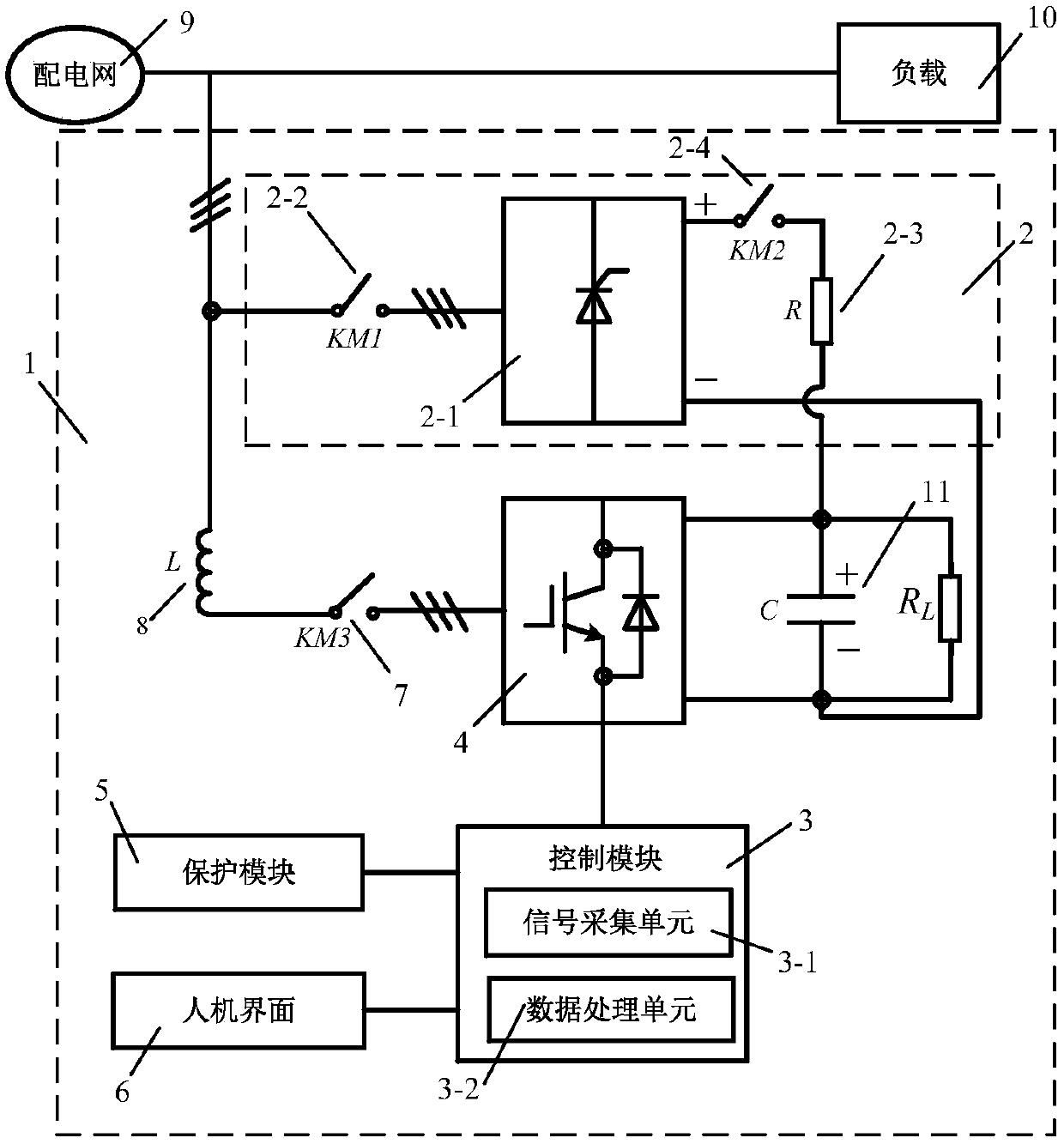
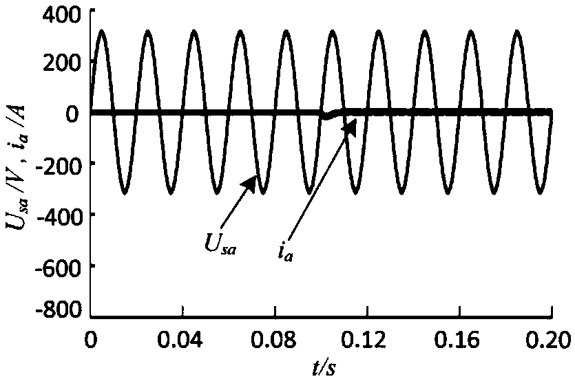
[0071] In this embodiment, the device start-up simulation experiment is carried out by using the condition of whether the pre-charging circuit 2 functions. image 3 and Figure 4 in, U sa Indicates the A-phase voltage of the distribution network 9, i a Indicates the A-phase current of the AC side of the power module 4 . use figure 1 The structural circuit in .

[0072] The pre-charging circuit 2 can be divided into four steps during the start-up process of the device connected to the grid:

[0073] Step 1: Precharge the DC side capacitor 11 of the power module 4; the device 1 uses a precharge circuit 2 composed of an uncontrollable rectifier bridge 2-1, a KM1 contactor 2-2, and a current limiting resistor 2-3. The control realizes charging the DC side capacitor 11 of the power module 4 . The specific operation is: close the KM1 contactor 2-2 and KM2 contactor 2-4 in the pre-charging circuit 2, so that the pre-charging circuit 2 can charge the DC side capacitor 11 of the ...

Embodiment 2

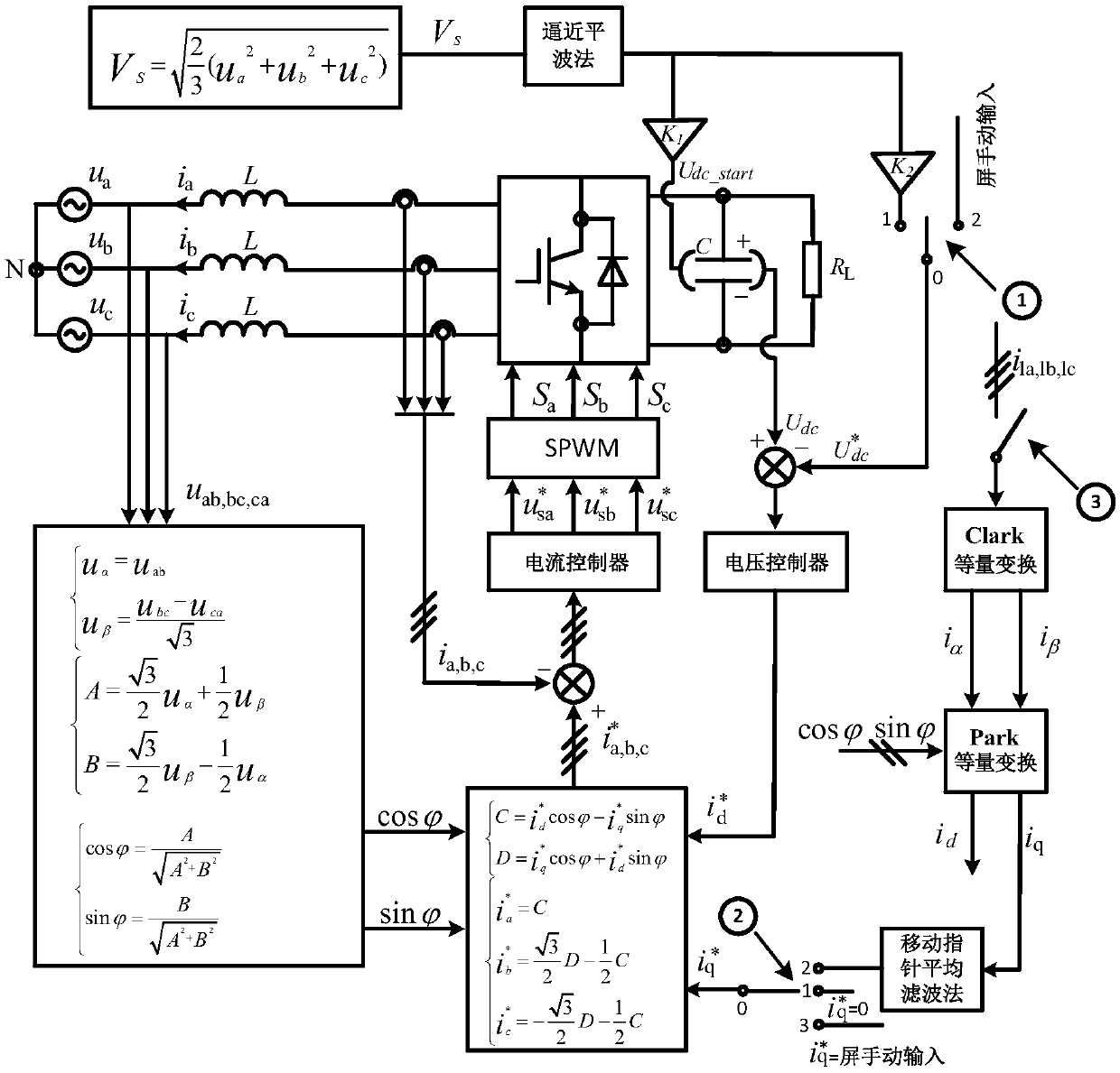
[0082] In this embodiment, the reactive current real-time detection and automatic compensation operation of the device 1 of the present invention are described; the reactive current real-time detection process of the device 1 of the present invention is as follows Figure 5 shown.

[0083] The first stage: calculate the reactive current in the load current; collect the load current i through the current transformer la,lb , the reactive current is calculated by coordinate equivalent transformation, but the reactive current at this time contains AC components in addition to DC components.

[0084] The second stage: filter the reactive current to obtain the reactive current command If it is not filtered, it may cause overcompensation, and even inject a large amount of harmonics into the power grid, and the compensation effect is poor. Therefore, it is considered to compensate after filtering.

[0085] The third stage: the device runs with load and performs automatic compensati...

Embodiment 3

[0089] In this embodiment, for the soft start gate valve voltage U of the device of the present invention dc_start and the DC side voltage target command of power module 4 Variable, to ensure that the compensation capability of device 1 is described, the specific implementation is as follows:

[0090] The soft-start gate valve voltage of device 1 and the DC-side voltage target command of power module 4 are both obtained by collecting the voltage signal of distribution network 9 and calculated by data processing unit 3-2. Changed properties;

[0091] The calculation formula of soft start gate valve voltage is:

[0092] u dc_start = K 1 ×V s(peak) (1)

[0093] In the formula, U dc_start Represents the soft-start gate valve voltage of device 1, that is, the DC side voltage value of power module 4 when device 1 starts; V s(peak) Represents the peak value of the 9-phase voltage of the distribution network; K 1 represents user-defined coefficients, but K 1 Generally, the...


PUM


Abstract

The invention discloses a static synchronous compensator device of a three-phase three-bridge-arm power distribution network and a control method. The static synchronous compensator device is specially composed of a pre-charging circuit, a control module, a power module, a protection module and a human-computer interaction interface. The static synchronous compensator device has the advantages that the problem of impact current produced by high-voltage network-hanging start and voltage rise and fall of the device is solved by utilizing forward characteristics of the pre-charging circuit and an inverse proportional function; the device has a friendly human-computer interaction interface, the selectable reactive compensation mode and operation information display of the device can be achieved, and the device is more humanized and intelligentized; 3, the idle handling capacity can be ensured according to a power distribution network voltage environment; 4, a traditional lowpass filtering method is replaced by adopting a movable pointer average filter method and a novel approach smoothing crest method, the operating efficiency of an algorithm routine is improved, and the problem of reactive current detection delaying is eliminated. The cost of the device is reduced, the technical contents of the reactive compensation device are enriched, and the device has a certain reference value on engineering application.

Description

technical field [0001] The invention relates to the technical field of reactive power compensation devices, in particular to a static synchronous compensator device and a control method for a three-phase three-arm distribution network. Background technique [0002] Currently, off-the-shelf static synchronous compensator devices exist, but they are expensive and the engineering techniques are not disclosed. The static synchronous compensator has been favored by scholars at home and abroad because of its fast reactive power compensation response speed and wide continuous adjustment range. [0003] The currently disclosed static synchronous compensator prototype device for distribution network still has many deficiencies, such as: the device cannot be directly connected to the grid to start or generate a huge inrush current at the moment of start-up, cannot complete real-time detection of reactive current, single compensation capacity and fixed The given instructions lead to l...

Claims


Application Information

Patent Timeline
Patent Type & Authority Patents(China)
IPC IPC(8): H02J3/18
CPCH02J3/1842Y02E40/10
Inventor 杨达亮徐胜光吴宁卢子广吴玮钦王慧
Owner GUANGXI UNIV
Why Eureka
Try Eureka