Multifunctional battery charging device

A battery charging and multi-functional technology, applied in battery circuit devices, different battery charging, circuit devices, etc., can solve the problems of complicated winding, inconvenience, and complicated structure, and achieve a good user experience, reasonable structure, and improved use. The effect of efficiency

Inactive Publication Date: 2017-06-13
陈萍
View PDF4 Cites 2 Cited by
  • Summary
  • Abstract
  • Description
  • Claims
  • Application Information

AI Technical Summary

Problems solved by technology

[0003] Battery charger is an electronic device for charging rechargeable batteries used in electric vehicles, electric tools, video games, notebooks, photovoltaics, digital and small portable electronic devices and electronic appliances. It generally consists of a casing, a power conversion part, a charging detection part, a charging protection part, etc Composition, the battery chargers commonly used now can generally only be connected to one charging position, even if there are a few that can be connected to multiple charging positions, they can only be connected to multiple charging positions of the same voltage, but whether it is a socket or a battery charging The structure of the device box is relatively cumbersome, and it cannot be effectively fixed during use, making it inconvenient to use. At the same time, during use, the traditional sockets are all wired sockets. This design does not take into account the need for power cords It is used under the condition of lead wires, and it also causes messy winding, which brings bad experience to users, and the structure and function are simple and single, which cannot meet the needs of people's living standards.

Method used


Image

  • Multifunctional battery charging device
  • Multifunctional battery charging device
  • Multifunctional battery charging device

Examples


Embodiment Construction

[0014] The following will clearly and completely describe the technical solutions in the embodiments of the present invention with reference to the accompanying drawings in the embodiments of the present invention. Obviously, the described embodiments are only some, not all, embodiments of the present invention. Based on the embodiments of the present invention, all other embodiments obtained by persons of ordinary skill in the art without making creative efforts belong to the protection scope of the present invention.

[0015] In the description of the present invention, it should be noted that the orientation or positional relationship indicated by the terms "vertical", "upper", "lower" and "horizontal" are based on the orientation or positional relationship shown in the drawings, and are only for It is convenient to describe the utility and simplify the description, but does not indicate or imply that the device or element referred to must have a specific orientation, be con...


PUM


Abstract

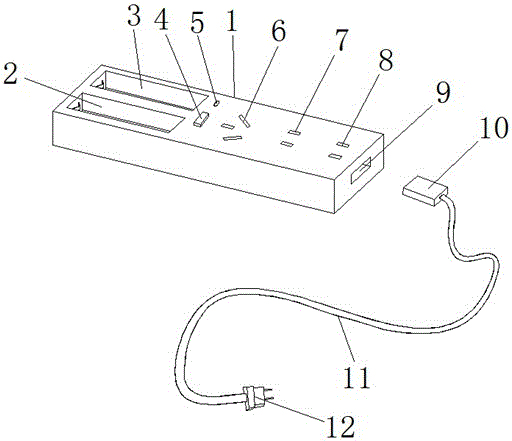
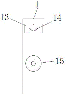
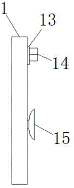
The invention discloses a multifunctional battery charging device including a socket box and a power line. The upper end face of the socket body is provided with a first battery groove. The other side of a first jack is provided with a second jack. One side of the second jack is provided with a third jack. The tail end of the socket box is provided with a wiring hole. A connection base plate is connected to the back face of the socket box fixedly. A second plug is mounted on the connection base plate. A sucker is mounted in the middle position of the back face of the socket box. One end of the power line is equipped with a connector while the other end of the power line is connected with the first plug electrically. The multifunctional battery charging device is reasonable in structure and can charge a lithium battery when serving as a socket. At the same time, two connection modes, namely, wired connection and wireless connection, can be provided for a user through different wiring ways. The sucker arranged on the back face can solve a problem of fixation of the patch board effectively, so that the patch board placement disorder is avoided during use and a user can have better use experience.

Description

technical field [0001] The invention relates to the technical field of battery equipment, in particular to a multifunctional battery charging device. Background technique [0002] Lithium-ion battery is a secondary battery (rechargeable battery) that mainly relies on lithium ions to move between positive and negative electrodes to work. During the charging and discharging process, Li+ intercalates and deintercalates back and forth between the two electrodes: when charging, Li+ is deintercalated from the positive electrode, intercalated into the negative electrode through the electrolyte, and the negative electrode is in a lithium-rich state; the opposite is true during discharge. [0003] Battery charger is an electronic device for charging rechargeable batteries used in electric vehicles, electric tools, video games, notebooks, photovoltaics, digital and small portable electronic devices and electronic appliances. It generally consists of a casing, a power conversion part, ...

Claims


Application Information

Patent Timeline
Patent Type & Authority Applications(China)
IPC IPC(8): H02J7/00
CPCH02J7/0036H02J7/0042H02J7/0047H02J7/0049
Inventor 王爽
Owner 陈萍
Why Eureka
Try Eureka