Inner stator permanent-magnet moving iron core-type linear oscillation motor

A technology of oscillating motor and inner stator, applied in electromechanical devices, electrical components, etc., can solve the problems of high spring stiffness requirements, large iron core mover mass, weakened reliability, etc., so as to improve reliability and overload capacity. And the effect of service life, avoid high temperature demagnetization, compact structure

Active Publication Date: 2017-06-13
HUAZHONG UNIV OF SCI & TECH
View PDF5 Cites 9 Cited by
  • Summary
  • Abstract
  • Description
  • Claims
  • Application Information

AI Technical Summary

Problems solved by technology

But the ensuing problem is that both the permanent magnet and the armature winding are on the same heating unit, and the heat generated by the armature is easily transmitted to the permanent magnet, which may even lead to its irreversible demagnetization in severe cases, seriously restricting the motor. overload capability, impairing its reliability
In addition, the mass of the iron-core mover is relatively large, which requires high rigidity of the photo spring, which is also a major factor restricting the application of this type of linear oscillating motor

Method used


Image

  • Inner stator permanent-magnet moving iron core-type linear oscillation motor
  • Inner stator permanent-magnet moving iron core-type linear oscillation motor
  • Inner stator permanent-magnet moving iron core-type linear oscillation motor

Examples


Embodiment Construction

[0043] In order to make the object, technical solution and advantages of the present invention clearer, the present invention will be further described in detail below in conjunction with the accompanying drawings and embodiments. It should be understood that the specific embodiments described here are only used to explain the present invention, not to limit the present invention. In addition, the technical features involved in the various embodiments of the present invention described below can be combined with each other as long as they do not constitute a conflict with each other.

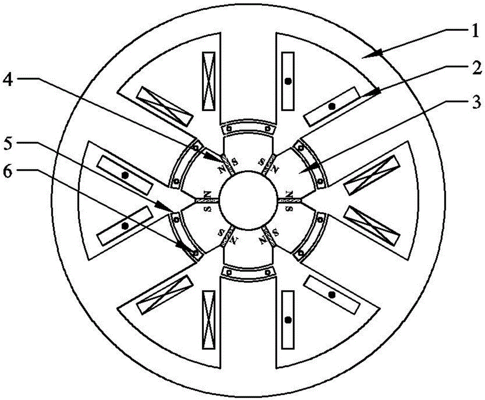
[0044] figure 1 It is a schematic diagram of stator and mover iron core punching pieces, permanent magnet arrangement and coil winding direction in an implementation example of the present invention. It includes an outer stator core punch 1 , a coil 2 , an inner stator core punch 3 , a permanent magnet 4 , a mover core punch 5 and a mover core positioning through hole 6 . Among them, the outer...


PUM


Abstract

The invention discloses an inner stator permanent-magnet moving iron core-type linear oscillation motor which comprises an inner stator iron core, an outer stator iron core, a rotor iron core, a cage-type rotor iron core bracket, permanent magnets, an armature winding and a resonant spring, wherein multiple permanent magnets are uniformly embedded into a yoke of each annular stator iron core of the inner stator iron core along the peripheral direction; multiple coils for forming the armature winding are wound on outer stator iron core teeth; the rotor iron core comprises multiple segments of arc-shaped iron cores; various segments of arc-shaped iron cores are fixedly connected into a whole by using the cage-type rotor iron core bracket; the whole is arranged in an air gap between the inner stator iron core and the outer stator iron core; and the resonant spring sleeves the part between the cage-type rotor iron core bracket and an end cover. The permanent magnets do not participate in reciprocating vibration, so that the security, the reliability and the robustness of the motor can be greatly improved; the permanent magnets and the armature winding are put on different stators, so that high-temperature magnetic losses of the permanent magnets can be avoided; the mass of a rotor is reduced; the requirements of a system on the rigidity of the resonant spring can be reduced; and improvement of the resonant frequency is facilitated.

Description

technical field [0001] The invention belongs to the field of linear oscillating motors, and more specifically relates to a motor in which two sets of inner and outer stators are used, and permanent magnets and armature windings are separately placed on the inner and outer stators, and the moving and force-bearing parts are dynamic Sub-core linear oscillating motor. Background technique [0002] For a long time, linear reciprocating motion has been mainly realized by traditional rotating motor + crank and other transmission mechanisms. This method has been criticized for its low efficiency and power factor, complex structure, and bulky volume. The use of permanent magnet linear oscillating motors to achieve linear reciprocating motion can not only save intermediate transmission mechanisms such as cranks, but also significantly improve efficiency and power factor, so it has received widespread attention. [0003] Permanent magnet linear oscillating motors can be divided into ...

Claims


Application Information

Patent Timeline
Patent Type & Authority Applications(China)
IPC IPC(8): H02K33/16H02K33/02
CPCH02K33/02H02K33/16
Inventor 徐伟李想
Owner HUAZHONG UNIV OF SCI & TECH
Why Eureka
Try Eureka