
Autofocus method and device based on dual camera system

An auto-focus, dual-camera technology, applied in the components, image analysis, image communication, etc. of the TV system, which can solve the problem of not taking into account the differences of the dual-camera modules, the deviation of the clarity of the dual-camera public field of view, the focus difference, etc. problem, to achieve the effect of achieving the consistency of sharpness and optimizing the imaging effect

Active Publication Date: 2019-08-27
X CHIP MICROELECTRONICS TECH CO LTD
View PDF5 Cites 0 Cited by
  • Summary
  • Abstract
  • Description
  • Claims
  • Application Information

AI Technical Summary

Problems solved by technology

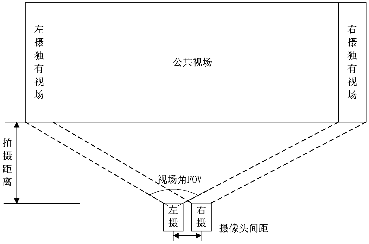
Since the difference in the field of view angles of the two camera units in the dual-camera system is not considered, if there is a target object with a texture different from the common field of view in the unique field of view of the two camera units, it will lead to a deviation in the contrast statistics , and finally the difference in focus points, resulting in a large deviation in the definition of the dual-camera public field of view, making it impossible to perform image-based matching
In addition, because the difference between the left and right of the dual camera module is not taken into account, even if the same parameters are used, completely different sharpness and focus positions can be obtained without correction.

Method used


Image

  • Autofocus method and device based on dual camera system
  • Autofocus method and device based on dual camera system
  • Autofocus method and device based on dual camera system

Examples


Embodiment 1

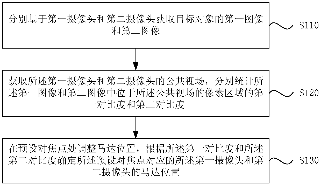
[0026] figure 1 It is a flow chart of a method for calibrating autofocus parameters based on a dual-camera system provided in Embodiment 1 of the present invention. The method can be performed by a calibrating device for autofocus parameters based on a dual-camera system. The device can use hardware and It may be implemented in a software manner, and may generally be independently configured in a user terminal to implement the method in this embodiment.

[0027] Specifically, the method of this embodiment includes:

[0028] S110. Acquire a first image and a second image of a target object based on the first camera and the second camera respectively.

[0029] Wherein, the target object may be the entire scene area to be photographed, or a part of objects or a single object in a multi-object scene, or even a part of a single object. For example, based on the images with the depth of field effect captured by the first camera and the second camera, the target object may be under...

Embodiment 2

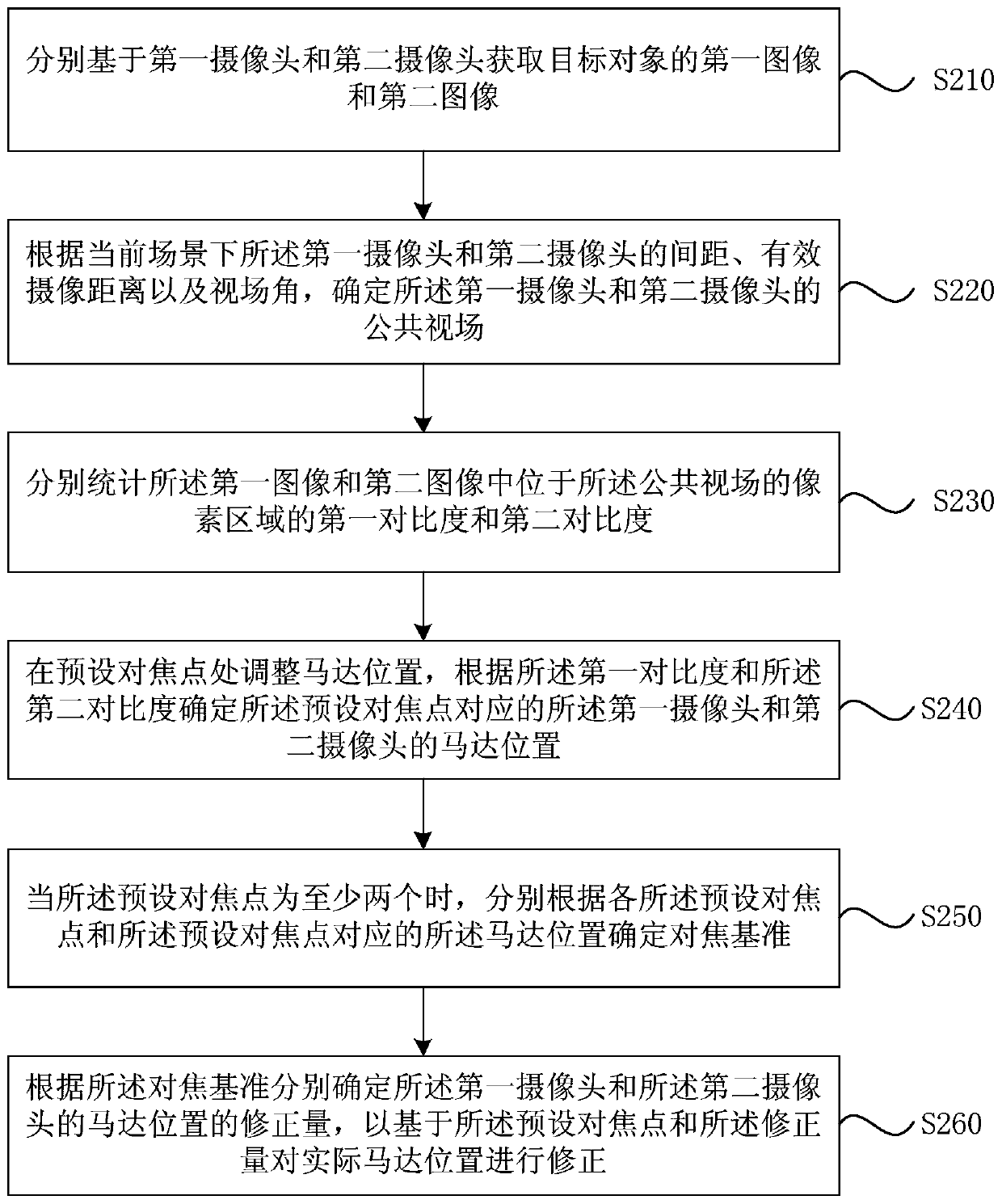
[0038] Figure 2A A schematic flowchart of a calibration method for autofocus parameters based on a dual-camera system provided in Embodiment 2 of the present invention, as shown in Figure 2A As shown, in this embodiment, on the basis of the foregoing embodiments, it is optional that the acquiring the common field of view of the first camera and the second camera includes: according to the current scene of the first camera and the second camera The distance, the effective camera distance, and the field of view angle determine the common field of view of the first camera and the second camera.

[0039] On the basis of the above-mentioned technical solutions, the calibration method of the autofocus parameters based on the dual camera system in this embodiment may further include: when there are at least two preset focus points, respectively according to each of the preset focus points The focal point and the motor position corresponding to the preset focus point determine a focu...

Embodiment 3

[0062] image 3 A schematic flowchart of a method for calibrating autofocus parameters based on a dual-camera system provided in Embodiment 3 of the present invention, as shown in image 3 As shown, in this embodiment, on the basis of the above-mentioned embodiments, it is optional that the determining the focus reference according to each of the preset focus points and the motor positions corresponding to the preset focus points includes: according to the The preset focus point and the motor position corresponding to the preset focus point determine a first focus curve of the first camera and a second focus curve of the second camera; combine the first focus curve and the second focus curve 2. Fitting the focus curve to obtain the focus reference.

[0063] On the basis of the above technical solutions, the method for calibrating autofocus parameters based on the dual camera system in this embodiment may further include: determining the current motor position according to the...


PUM


Abstract

Embodiments of the present invention provide a method and device for calibrating autofocus parameters based on a dual-camera system, wherein the method includes: acquiring a first image and a second image of a target object based on the first camera and the second camera respectively; acquiring For the common field of view of the first camera and the second camera, respectively count the first contrast and the second contrast of the pixel areas located in the common field of view in the first image and the second image; at the preset focus point Motor positions are adjusted, and motor positions of the first camera and the second camera corresponding to the preset focus point are determined according to the first contrast ratio and the second contrast ratio. According to the technical solution of the embodiment of the present invention, by separately counting the first contrast and the second contrast of the pixel area located in the common field of view in the first image and the second image, the common statistics of the dual-camera system images are used to cooperatively control the dual-camera system. Focusing achieves the clarity consistency of the dual-camera system.

Description

technical field [0001] Embodiments of the present invention relate to the technical field of electronic equipment, and in particular to an autofocus method and device based on a dual camera system. Background technique [0002] Due to the powerful functions it brings, such as background blur, post-focus, optical zoom, and dark state enhancement, the dual-camera system (hereinafter referred to as "dual-cam") has gradually become the standard configuration of smartphones. [0003] The matching algorithm is the main factor affecting the accuracy and effect of the dual-camera algorithm. The matching algorithm is a search algorithm based on the grayscale, color, and sharpness of the image. The matching algorithm will perform dual-camera view matching based on the above three dimensions of image evaluation. Only when the matching algorithm is used to accurately find out the corresponding relationship between the pixels between the two images, can the cross information of the two ...

Claims


Application Information

Patent Timeline
Patent Type & Authority Patents(China)
IPC IPC(8): H04N5/232G06T7/80
CPCH04N23/67
Inventor 江浩郭鑫魏孜宸
Owner X CHIP MICROELECTRONICS TECH CO LTD
Learn More