
Wireless network simulation method and system

A simulation method and wireless network technology, applied in the field of communication, can solve the problems of difficult adjustment, huge time and labor cost, time-consuming and so on.

Active Publication Date: 2017-06-13
GCI SCI & TECH
View PDF4 Cites 14 Cited by
  • Summary
  • Abstract
  • Description
  • Claims
  • Application Information

AI Technical Summary

Problems solved by technology

[0002] Most geographical environments (such as office buildings or user homes) are covered with wireless networks. To build a wireless communication network environment, outdoor base stations and indoor signal generators need to be deployed in the geographical environment. After the outdoor base stations and indoor signal generators are fixed at the corresponding positions, The staff uses the signal detection device to detect whether the geographical environment is completely covered by the wireless network. If the coverage is not in place, it is necessary to adjust the position of the outdoor base station or the indoor signal generator until the staff confirms that the geographical environment is completely covered by the wireless network. Repeat this process Layout of outdoor base stations and indoor signal generating devices will take a lot of time and is very cumbersome, and outdoor base stations and indoor signal generating devices are usually installed in higher geographical locations, making adjustment difficult, especially for large geographical environments such as large office buildings, outdoor base stations and There are a large number of indoor signal generators, and it will take a lot of time and labor costs to repeatedly detect signals everywhere and adjust the position of outdoor base stations or indoor signal generators

Method used


Image

  • Wireless network simulation method and system
  • Wireless network simulation method and system
  • Wireless network simulation method and system

Examples


Embodiment Construction

[0022] In order to make the object, technical solution and advantages of the present invention clearer, the present invention will be further described in detail below in conjunction with the accompanying drawings and embodiments. It should be understood that the specific embodiments described here are only used to explain the present invention, not to limit the present invention.

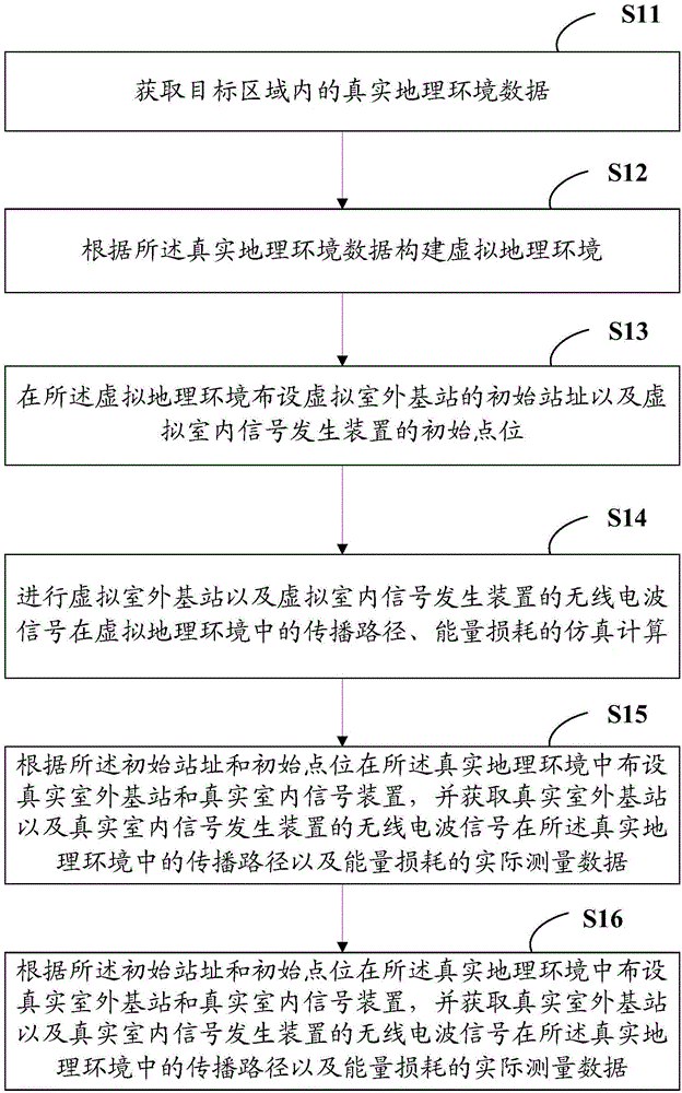
[0023] see figure 1 , figure 1 It is a schematic flowchart of a wireless network simulation method of the present invention.

[0024] The wireless network simulation method in this embodiment may include the following steps:

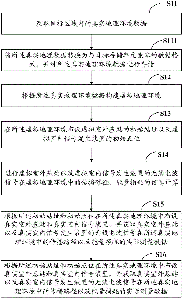
[0025] S11: Obtain real geographical environment data in the target area;

[0026] S12: Construct a virtual geographic environment according to the real geographic environment data;

[0027] S13: Layout the initial site of the virtual outdoor base station and the initial location of the virtual indoor signal generating device in the virtual geographical environment;

[0...


PUM


Abstract

The invention provides a wireless network simulation method and system. The method comprises the following steps: obtaining the real geographical environment data in a target area, constructing a virtual geographical environment based on the real geographical environment data, deploying an initial site location of a virtual outdoor base station and an initial point location of a virtual indoor signal generating device in the virtual geographical environment, then implementing simulation calculation on the propagation path and energy loss of radio wave signals of the virtual outdoor base station and the virtual indoor signal generating device in the virtual geographical environment, and if the radio wave signals of the virtual outdoor base station and the virtual indoor signal generating device can cover the virtual geographical environment, deploying a real outdoor base station and a real indoor signal device in the real geographical environment according to the initial site location and the initial point location. Thereby, the process of repeatedly detecting the wireless signals in the geographical environment and adjusting the locations of the outdoor base station and the indoor antenna is not required, simple and convenient operations can be achieved, and the time and manpower cost can be saved.

Description

technical field [0001] The invention relates to the field of communication technology, in particular to a wireless network simulation method and system. Background technique [0002] Most geographical environments (such as office buildings or user homes) are covered with wireless networks. To build a wireless communication network environment, outdoor base stations and indoor signal generators need to be deployed in the geographical environment. After the outdoor base stations and indoor signal generators are fixed at the corresponding positions, The staff uses the signal detection device to detect whether the geographical environment is completely covered by the wireless network. If the coverage is not in place, it is necessary to adjust the position of the outdoor base station or the indoor signal generator until the staff confirms that the geographical environment is completely covered by the wireless network. Repeat this process Layout of outdoor base stations and indoor...

Claims


Application Information

Patent Timeline
Patent Type & Authority Applications(China)
IPC IPC(8): H04W16/22H04W24/06
CPCH04W16/22H04W24/06Y02D30/70
Inventor 朱南皓张昕李建中肖胜笔程敏余艺
Owner GCI SCI & TECH
Learn More