
Electrical cabinet

A technology for electrical cabinets and electrical components, applied in the field of electrical cabinets, to achieve the effect of improving the problem of dust pollution

Active Publication Date: 2018-01-19
JIANGXI SANLONG ELECTRICAL
View PDF4 Cites 0 Cited by
  • Summary
  • Abstract
  • Description
  • Claims
  • Application Information

AI Technical Summary

Problems solved by technology

[0003] The main purpose of the present invention is to provide an electrical cabinet, aiming at improving the heat dissipation effect of the electrical cabinet and reducing the dust pollution caused by heat dissipation

Method used


Image

  • Electrical cabinet
  • Electrical cabinet
  • Electrical cabinet

Examples


Embodiment Construction

[0021] The following will clearly and completely describe the technical solutions in the embodiments of the present invention with reference to the accompanying drawings in the embodiments of the present invention. Obviously, the described embodiments are only part of the embodiments of the present invention, not all of them. Based on the embodiments of the present invention, all other embodiments obtained by persons of ordinary skill in the art without creative efforts fall within the protection scope of the present invention.

[0022] It should be noted that if there is a directional indication (such as up, down, left, right, front, back...) in the embodiment of the present invention, the directional indication is only used to explain the position in a certain posture (as shown in the accompanying drawing). If the specific posture changes, the directional indication will also change accordingly.

[0023] In addition, if there are descriptions involving "first", "second" and ...


PUM


Abstract

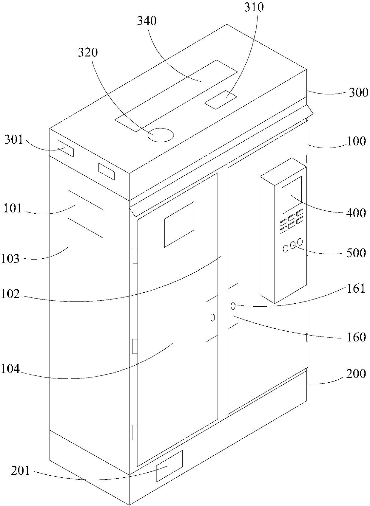
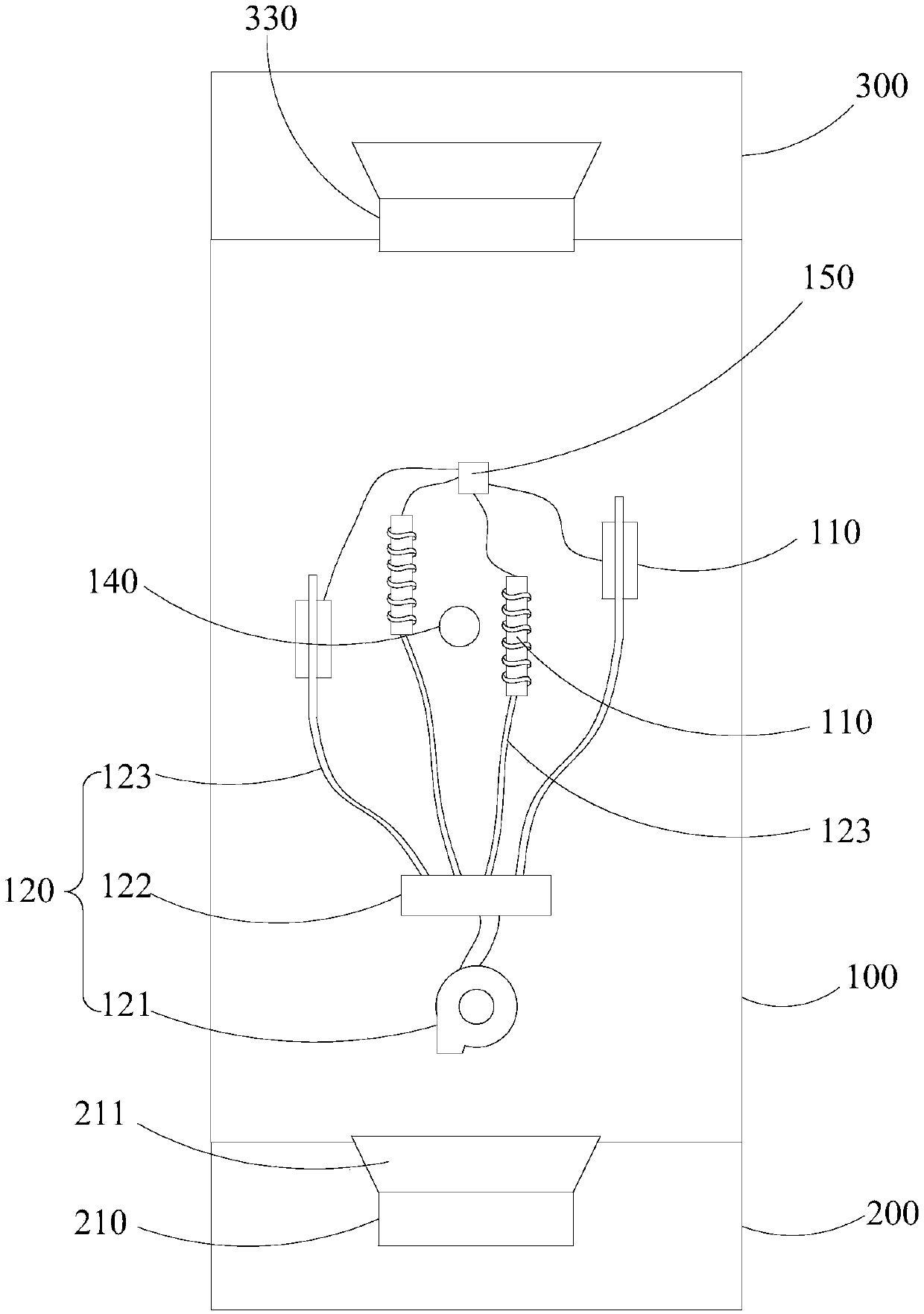
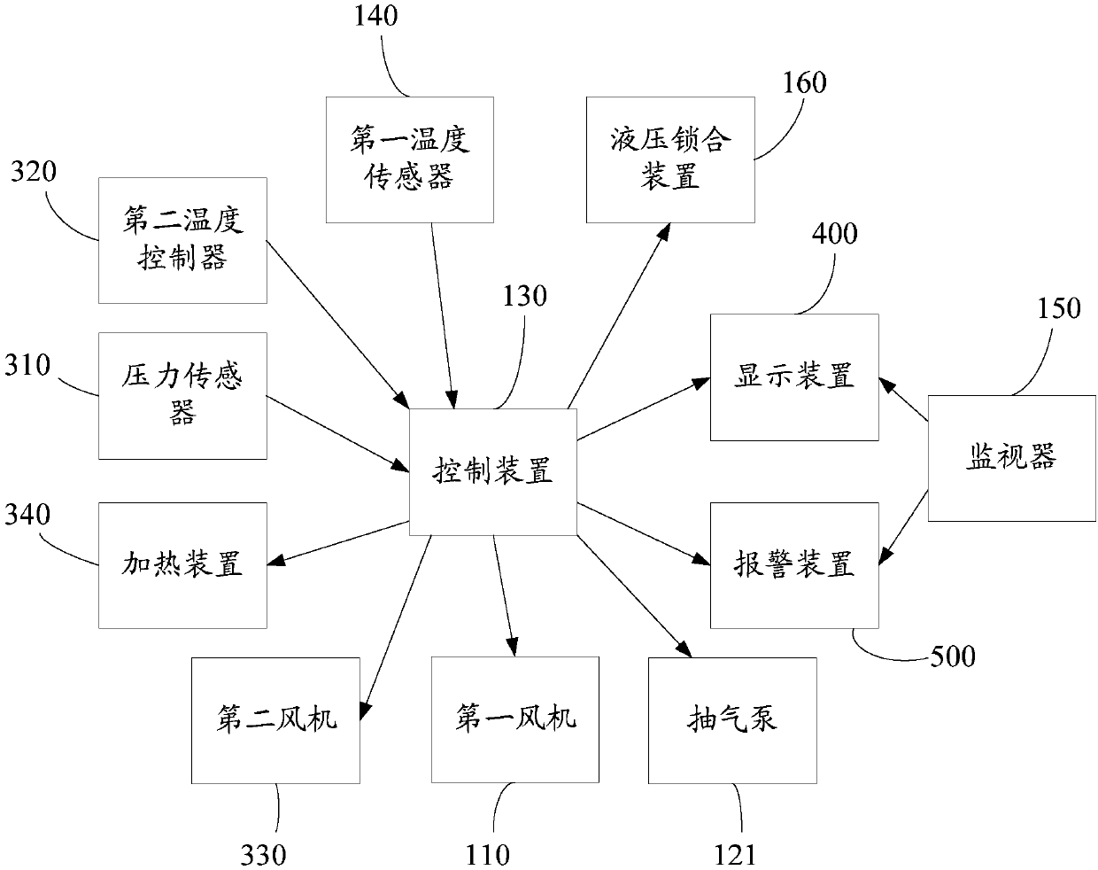
The invention discloses an electrical cabinet. The electrical cabinet comprises a main cabinet body and a lower cabinet body arranged below the main cabinet body; the lower cabinet body is provided with an air inlet, the air inlet is covered with a filter net, the middle-upper portion of the main cabinet body is provided with a plurality of heat radiating windows communicated with an accommodating space, the lower cabinet body is provided with a first fan, a mounting plate is arranged in the accommodating space, the mounting plate is provided with a plurality of electrical elements and at least one local cooling apparatus; and the local cooling apparatus comprises an air pump, a distribution pipeline and a plurality of air spray pipelines, and an air sucking port of the air pump is arranged adjacent and aligned to an air outlet of the fan. According to the technical scheme, the heat radiation effect of the electrical cabinet can be improved, and the dust pollution problem caused by the heat radiation can be reduced at the same time.

Description

technical field [0001] The invention relates to the technical field of electrical equipment cabinets, in particular to an electrical cabinet. Background technique [0002] Under normal circumstances, the heat dissipation method of the electrical cabinet is to set the air intake hole under the front door or the side wall of the cabinet body, set the exhaust port above, install the exhaust fan on the exhaust port, and mechanically force the exhaust from the cabinet. The body discharges hot air to the outside to achieve the purpose of heat dissipation. The above method of exhaust and heat dissipation is not only not very effective, it cannot focus on heat dissipation of overheated components, and it is also prone to other problems, for example, the dust and other pollutants brought in from the air inlet are easy to move upward with the airflow , and adhere to the surface of components or insulating parts to form dirt, causing safety accidents such as creepage and pollution fla...

Claims


Application Information

Patent Timeline
Patent Type & Authority Patents(China)
IPC IPC(8): H05K7/20
CPCH05K7/20554H05K7/207
Inventor 南进喜吕江泽聂志萍雷国亮邓爱兵刘常法易风游琪
Owner JIANGXI SANLONG ELECTRICAL
Learn More