
Method for positioning marine main engine foot bolt hole

A technology of foundation bolt holes and ship's main engine, which is applied to ship components, ship construction, ships, etc., can solve the problems of difficult to find deviations, the positioning deviation of the first footing bolt holes of the main engine, and increase the difficulty of positioning, etc., to achieve convenient management. , to ensure the quality of ship products, to ensure the effect of installation dimensional accuracy and performance

Inactive Publication Date: 2017-06-16
HUDONG ZHONGHUA SHIPBUILDINGGROUP
View PDF3 Cites 12 Cited by
  • Summary
  • Abstract
  • Description
  • Claims
  • Application Information

AI Technical Summary

Problems solved by technology

Since the base panel of the main engine is not on the same plane as the center line of the shaft system, there is a height difference, which increases the difficulty of its positioning. Therefore, a reference object is needed to "lead" the axial dimension to the main engine base through this reference object. On the seat panel, it can usually be realized by setting a channel steel target at a certain distance behind the first foot bolt hole of the main engine, but the verticality of the channel steel target and the main engine base panel and its own flatness will cause the The positioning deviation of a foot bolt hole can sometimes reach more than ten millimeters
The key point of the problem is that the deviation is often not easy to find. It can only be found by measuring the distance between the rear end face of the stern tube and the front face of the propeller after the shafting and the main engine are hoisted in place, but it is too late. How to eliminate the deviation in " It is particularly important in the embryonic stage. Therefore, there is an urgent need for an inspection method for the positioning of the ship's main engine to achieve accurate positioning of the ship's main engine.

Method used


Image

  • Method for positioning marine main engine foot bolt hole
  • Method for positioning marine main engine foot bolt hole
  • Method for positioning marine main engine foot bolt hole

Examples


Embodiment

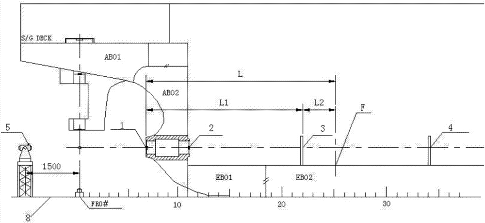
[0030] The practical application of the present invention will be specifically described below with the positioning steps of bolt holes of the main engine of a 76,000-ton bulk carrier.

[0031] The length of the shaft system in this embodiment is about 13.2m, the external dimensions of the main engine: 8700mm×7500mm×7700mm (length×width×height), the positioning accuracy of the main engine: axial -2~+5mm, lateral ±2mm.

[0032] Note: The units involved in the dimensions in the following steps are mm by default unless otherwise specified.

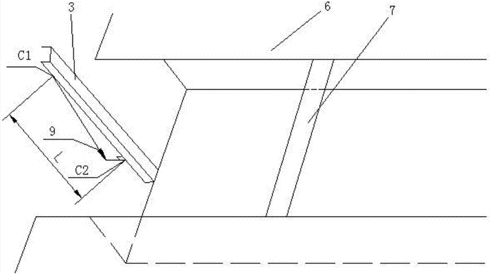
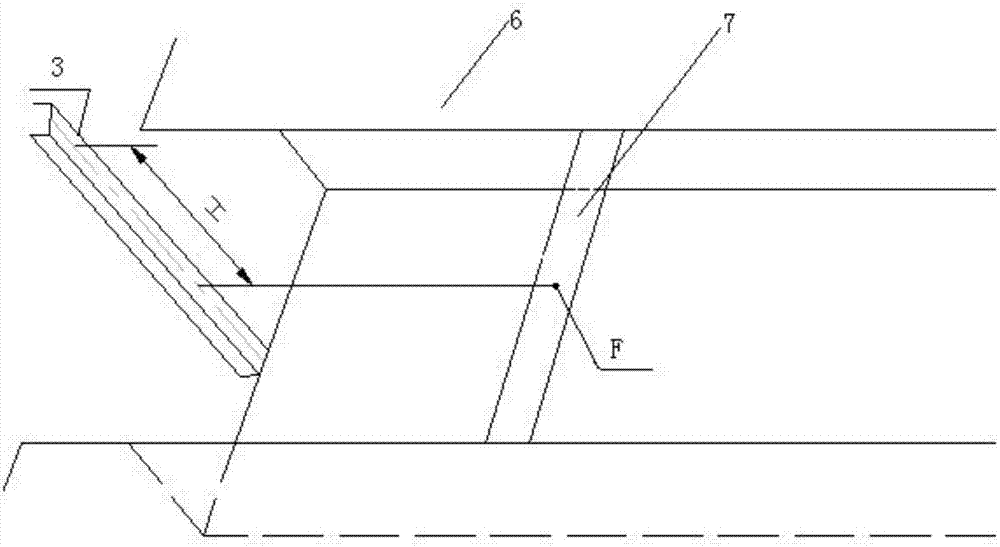
[0033] see Figure 1 to Figure 4 , the invention discloses a positioning method for anchor bolt holes of a ship main engine, which is characterized in that it comprises the following steps:

[0034] In the first step, a coring target A1 is placed on the rear end of the stern tube, a coring target B2 is placed on the front end of the stern tube, and the up, down, left, and right positions of the coring target A1 and the coring target B2 are a...


PUM


Abstract

The invention discloses a method for positioning a marine main engine foot bolt hole. Firstly, a centering target A is placed at the rear end face of a stern shaft tube, a centering target B is placed at the front end face of the stern shaft tube, and the up, down, left and right positions of the centering target A and the centering target B are adjusted till the connecting line of the centers of the two targets coincide with an axial hole center line of the stern shaft tube; secondly, according to a marine midship line, a channel steel target C is installed at the rear end of a first foot bolt hole of a marine main engine, and the channel steel target C is required to be straight and perpendicular to a base plate; thirdly, the actual center line position of a shaft system is determined according to the center line of the stern shaft tube, and then the center of the channel steel target C is adjusted to be flush with the actual center line of the shaft system on the basis. By accurately positioning the marine main engine foot bolt hole, the installing size precision and usage performance of relevant accessories of the shaft system can be ensured, further the hidden danger that a seal behind the stern shaft tube produce oil leakage is avoided, the quality of ship products can be ensured, and a ship production cycle can be also ensured.

Description

technical field [0001] The invention belongs to the technical field of ship building, and relates to a positioning method for anchor bolt holes of a main engine of a ship. Background technique [0002] The axial positioning deviation of the main engine of the ship will directly determine the installation accuracy of the rear and rear seals of the stern tube (according to the requirements of the seal manufacturer, the allowable deviation range of the installation distance between the rear end of the stern tube and the front end of the propeller is -2~+5mm), If the installation accuracy is out of control, it is very likely to cause oil leakage in the rear seal of the stern tube when the shafting system is running in the future, which has happened from time to time in ships built in the past. Therefore, the axial positioning deviation of the main engine will directly affect the performance of the rear seal of the stern tube. In addition, the axial positioning deviation of the ...

Claims


Application Information

Patent Timeline
IPC IPC(8): B63B9/06
CPCB63B73/00
Inventor 马鸿顺张治军陈文汉
Owner HUDONG ZHONGHUA SHIPBUILDINGGROUP
Learn More