Gas-fired external water tube boiler

A water-tube boiler and water-tube technology, which is used in water heaters, lighting and heating equipment, fluid heaters, etc., can solve problems such as boiler water leakage, and achieve the effects of convenient manufacturing and maintenance, convenient water vapor separation, and large heat exchange area.

Pending Publication Date: 2017-06-16
HARBIN SANHE JIAMEI TECH DEV
View PDF0 Cites 0 Cited by
  • Summary
  • Abstract
  • Description
  • Claims
  • Application Information

AI Technical Summary

Problems solved by technology

[0002] At present, gas-fired boilers mostly adopt fire tube structure. In practical application, due to the drastic change of cold and heat, it is easy to cause water leakage in the boiler.

Method used


Image

  • Gas-fired external water tube boiler
  • Gas-fired external water tube boiler
  • Gas-fired external water tube boiler

Examples


Embodiment

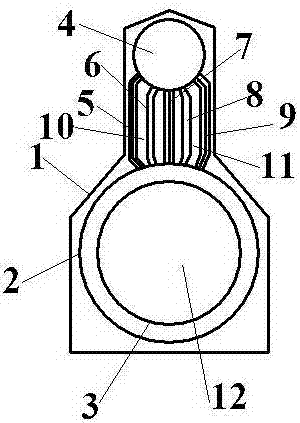
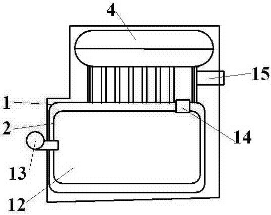
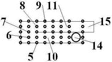
[0015] See attached figure 1 As shown, the boiler shell (1) wraps all the main heat exchange equipment inside, and is insulated with thermal insulation materials. The outer combustion chamber (2) and the combustion chamber (3) are water jackets. 2) It forms a furnace (12) with the combustion chamber (3). The combustion chamber (3) mainly conducts radiation heat exchange. A burner (13) is installed in the middle of the front of the furnace (12). The upper rear position is provided with a furnace hot flue gas outlet (14), and the upper drum (4) is set on the top of the boiler, passing through the right water pipe row (5), the right flue water pipe row (6), the middle water pipe row (7), The left flue water pipe row (8), the left water pipe row (9) and other five drainage pipes are connected to the combustion outdoor bladder (2), and the right water pipe row (5), the right flue water pipe row (6), and the middle water pipe row (7) ) Forms the return flue (10), which is composed of...


PUM


Abstract

The invention relates to a gas-fired external water tube boiler. The gas-fired external water tube boiler includes a boiler housing (1), a combustion chamber outside lining (2), a combustion chamber inside lining (3), an upper boiler barrel (4), a right water pipe row (5), a right flue water pipe row (6), a middle water pipe row (7), a left flue water pipe row (8), a left water pipe row (9), a return flue (10), an exhaust flue (11), a hearth (12), a burner (13), a hearth hot flue gas outlet (14) and a flue outlet (15).

Description

Technical field [0001] The invention relates to a gas external water tube boiler, which belongs to the field of boiler equipment. Background technique [0002] At present, gas boilers mostly adopt fire tube structure. In practical applications, due to the drastic changes in cold and heat, it is easy to cause boiler water leakage. Summary of the invention [0003] The invention relates to a gas-fired outer water tube boiler to realize the purpose of a gas boiler heated by an outer water tube structure. [0004] In order to achieve the above objectives, the present invention adopts the following technical solutions: [0005] A gas outer water tube boiler, comprising: boiler shell (1), combustion outdoor bladder (2), combustion chamber bladder (3), upper drum (4), right water pipe row (5), right flue water pipe row ( 6) Middle water pipe row (7), left flue water pipe row (8), left water pipe row (9), return flue (10), exhaust flue (11), furnace (12), burner (13) , Furnace hot flue gas...

Claims


Application Information

Patent Timeline
IPC IPC(8): F24H1/44F24H9/00F24H9/18
Inventor 高洁淡博
Owner HARBIN SANHE JIAMEI TECH DEV
Why Eureka
Try Eureka