Emergency in-vitro cooling device

A cooling device and emergency technology, applied in the field of medical devices, can solve the problems of single cooling method, rigid use method, time-consuming and labor-intensive alcohol, etc., and achieve the effect of good cooling effect, good cooling effect and fast cooling speed.

Active Publication Date: 2017-06-20
欧阳艳红
View PDF11 Cites 8 Cited by
  • Summary
  • Abstract
  • Description
  • Claims
  • Application Information

AI Technical Summary

Problems solved by technology

Fever symptoms are common in emergency departments. Physical cooling is the first choice for fever. Medical staff usually apply ice packs directly to patients or wipe them with alcohol repeatedly during physical cooling. It is time-consuming an

Method used


Image

  • Emergency in-vitro cooling device
  • Emergency in-vitro cooling device

Examples


Example Embodiment

[0016] Example 1

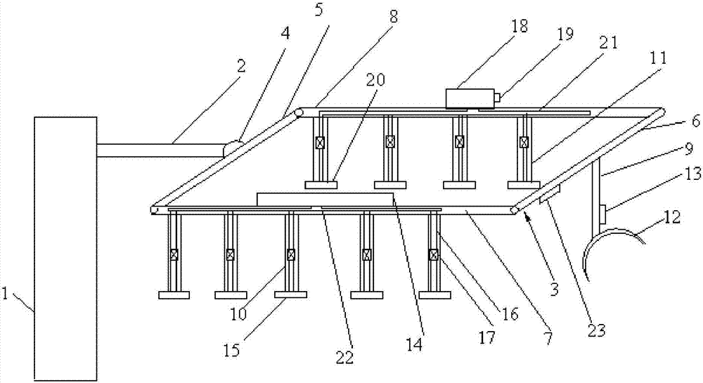
[0017] Such as figure 1 As shown, an emergency in vitro cooling device includes a fixed seat 1 and a bracket 3; a support rod 2 is provided on one side of the fixed seat 1, and the support rod 2 is a telescopic rod. The support rod 2 can be used to make the support 3 The position is adjusted so that the bracket 3 can be more flexibly aligned with the target part of the human body. The support 3 is rectangular, and the first cross bar 5 of the support 3 is connected to the support rod 2 through a rotary connector 4, so that the support 3 can be rotated at any angle, so that the support 3 can better match the body part; The second crossbar 6 of the bracket 3 is provided with a first branch rod 9, the first side rod 7 of the bracket 3 is provided with a plurality of second branch rods 10, and the second side rod 8 of the bracket 3 is One side is provided with a number of third branch rods 11, with multiple branch rods, so that the present invention can achieve a ...

Example Embodiment

[0019] Example 2

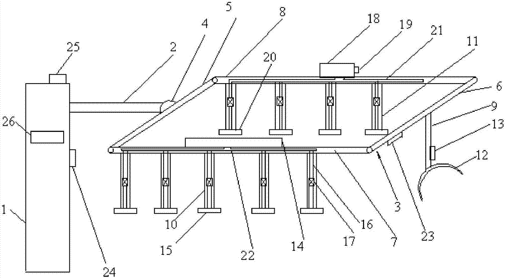
[0020] Such as figure 2 As shown, an emergency external cooling device includes a fixed seat 1, a bracket 3, a temperature measuring element 23, a PLC controller 24, a driving motor 25, and a display 26; the temperature measuring element 23 is an infrared thermometer, which does not need to touch the human body The body temperature of the patient is measured; the temperature measuring element 23, the driving motor 25 and the display 26 are respectively connected to the PLC controller 24, the body temperature measured by the temperature measuring element 23 is fed back to the PLC controller 24, and the PLC controller 24 controls the components according to the temperature information For cooling operation, the drive motor 25 is connected to the support 3, and the PLC controller 24 controls the drive motor 25 to drive the support 3 to move, so that the support 3 better matches the human body. A support rod 2 is provided on one side of the fixed seat 1, and a sl...


PUM


Abstract

The invention discloses an emergency in-vitro cooling device. The emergency in-vitro cooling device comprises a fixing base and a bracket, one side of the fixing base is connected with the bracket through a support rod, the bracket is rectangular, and cross rods and side rods of the bracket are provided with first branch rods, second branch rods and third branch rods respectively; each first branch rod is connected with an ice water bag, and each ice water bag is connected with a semiconductor refrigeration sheet; a first side rod is provided with a first container, each second branch rod is provided with a first wiping piece in a communicated mode, each first wiping piece is communicated with the first container through a first pipeline, and a first flow controller is arranged on each first pipeline; a second side rod is provided with a second container, the second container is connected with a thermostat, a second wiping piece is arranged on each third branch rod, each second wiping piece is communicated with the second container through a second pipeline, and a second flow controller is arranged on each second pipeline. According to the emergency in-vitro cooling device, a plurality of cooling modes and usage methods are integrated, and the device has the advantages of being convenient to use, good in cooling effect and suitable for different patients to use.

Description

technical field [0001] The invention relates to the technical field of medical devices, in particular to an emergency external cooling device. Background technique [0002] The emergency department is the department with the most concentrated critically ill patients, the most types of diseases, and the heaviest rescue task in the hospital. Fever symptoms are common in emergency departments. Physical cooling is the first choice for fever. Medical staff usually apply ice packs directly to patients or wipe them with alcohol repeatedly during physical cooling. It is time-consuming and labor-intensive, and some existing body temperature cooling devices have a single cooling method, and the use method is relatively rigid, so there is an urgent need for an emergency external cooling device to solve the above technical problems. Contents of the invention [0003] In view of this, the present invention provides an emergency in vitro cooling device to solve the above technical prob...

Claims


Application Information

Patent Timeline
IPC IPC(8): A61F7/00A61F7/10A61M35/00
CPCA61F7/00A61F7/10A61F2007/0007A61M35/00
Inventor 欧阳艳红韩旻君
Owner 欧阳艳红
Why Eureka
Try Eureka