Al technical title is built by PatSnap Al team. It summarizes the technical point description of the patent document.
A technology of automatic spraying and electromagnetic devices, applied in the direction of spraying devices, spraying devices, liquid spraying devices, etc., can solve problems such as air pollution, excessive paint spraying, difficult adhesion, etc., and achieve the effect of improving processing quality and ensuring uniformity
Inactive Publication Date: 2017-06-20
FANGZHOU COMM TECH TIANJIN CO LTD
View PDF0 Cites 1 Cited by
Summary
Abstract
Description
Claims
Application Information
AI Technical Summary
This helps you quickly interpret patents by identifying the three key elements:
Problems solved by technology
Method used
Benefits of technology
Problems solved by technology
[0002] The traditional spraying machine uses compressed air to atomize the paint, and the spray speed of the paint is generally 10 m / s. Such a fast spray speed leads to excessive spraying of the paint and serious rebound phenomenon, and brings back a large number of paint molecules causing The paint is scattered and flying, which not only wastes a lot of paint, but also causes serious pollution to the air. At the same time, the surface of the coating is prone to flaws
Due to the strong recoil force when spraying, the paint is not easy to adhere to the corners and edges of the workpiece, so it takes more time to spray, causing the nearby surface to sag
Method used
Image
Click on the blue label to locate the original text in one second.
Reading with bidirectional positioning of images and text.
Examples
Embodiment
[0034] In order to achieve the above object, the technical scheme adopted in the present invention is as follows:
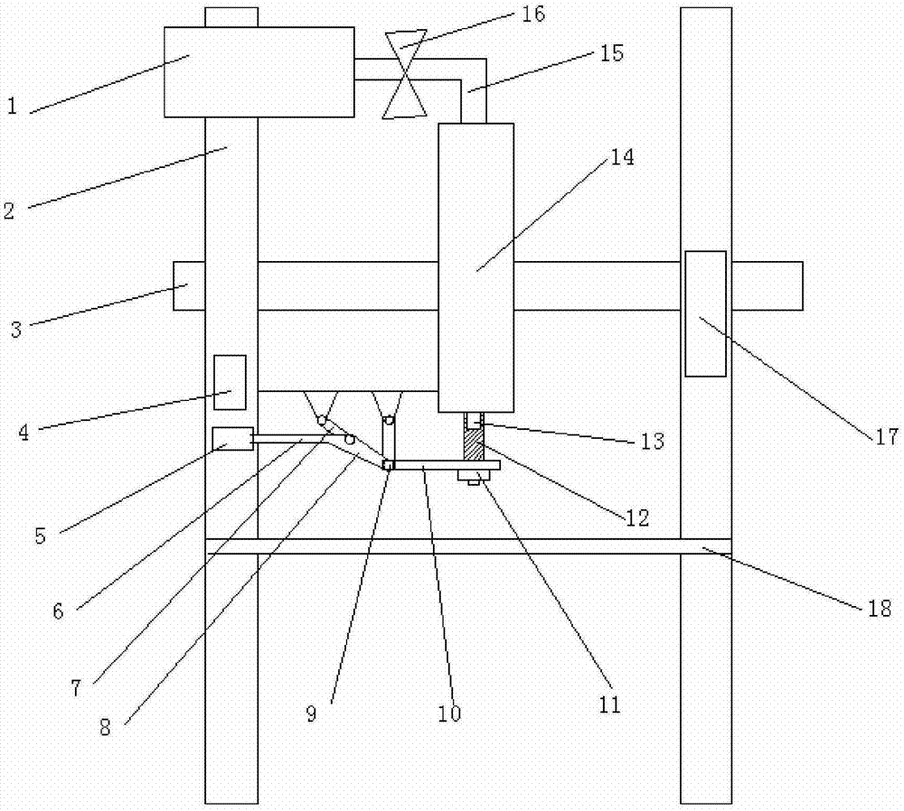
[0035] The automatic spraying device includes: storage tank 1, mounting plate leg 2, mounting plate 3, electromagnetic device 4, permanent magnet 5, handle 6, rod A7, rod B8, hinge 9, rod C10, fastening nut 11, nozzle cover 12. Nozzle 13, paint spray tank 14, paint spray tube 15, controllable valve 16, control device 17 and production line 18, the storage tank 1 is fixed on the left mounting plate leg 2, and is connected with the paint spray tank 14 through the paint spray tube 15, The paint spray pipe 15 is provided with a controllable valve 16, the paint spray can 14 is fixed on the mounting plate 3, and its lower end is provided with a nozzle 13, the electromagnetic device 4 is fixed on the leg 2 of the left mounting plate, and the end of the handle 6 is fixed with a permanent magnet 5, And connected with the rod B8, the two ends of the rod B8 are respectively...
PUM
Abstract
The invention belongs to the technical field of painting equipment, and in particular relates to an automatic spraying device. The automatic spraying device includes: a storage tank, a mounting plate leg, a mounting plate, an electromagnetic device, a permanent magnet, a handle, a rod A, a rod B, a hinge, and a rod C. Fastening nuts, nozzle covers, nozzles, paint spray tanks, paint spray pipes, controllable valves, control devices and production lines. The paint spraying tube is connected with the controllable valve, the paint spraying tank is fixed on the mounting plate, the nozzle is arranged at the lower end, and the electromagnetic device is fixed on the left side of the mounting plate. On the leg, the permanent magnet is fixed at the end of the handle. The present invention has a simple structure and strong pertinence, and can control the circulation of the paint. At the same time, the self-locking principle of the mechanism is used to realize the sealing or opening of the nozzle, which has wide application prospects. Suitable for promotion and application.
Description
technical field [0001] The invention belongs to the technical field of painting equipment, in particular to an automatic painting device. Background technique [0002] The traditional spraying machine uses compressed air to atomize the paint, and the spray speed of the paint is generally 10 m / s. Such a fast spray speed leads to excessive spraying of the paint and serious rebound phenomenon, and brings back a large number of paint molecules causing The paint is scattered and flying, which not only wastes a lot of paint, but also causes serious pollution to the air, and at the same time, the surface of the paint is prone to flaws. Due to the strong recoil force during spraying, the paint is not easy to adhere to the corners and edges of the workpiece, so it takes more time to spray, causing the nearby surface to sag. Contents of the invention [0003] Aiming at the deficiencies in the prior art, the purpose of the present invention is to provide an automatic spraying device...
Claims
Application Information
Patent Timeline
Application Date:The date an application was filed.
Publication Date:The date a patent or application was officially published.
First Publication Date:The earliest publication date of a patent with the same application number.
Issue Date:Publication date of the patent grant document.
PCT Entry Date:The Entry date of PCT National Phase.
Estimated Expiry Date:The statutory expiry date of a patent right according to the Patent Law, and it is the longest term of protection that the patent right can achieve without the termination of the patent right due to other reasons(Term extension factor has been taken into account ).
Invalid Date:Actual expiry date is based on effective date or publication date of legal transaction data of invalid patent.