Device for efficiently spraying electronic product with UV curing paint
A technology of spraying equipment and electronic products, which is applied in the direction of coating, spraying device, liquid spraying device, etc., and can solve problems such as inconvenient operation, low work efficiency, and physical health damage
- Summary
- Abstract
- Description
- Claims
- Application Information
AI Technical Summary
Problems solved by technology
Method used
Image

Examples
Embodiment 1
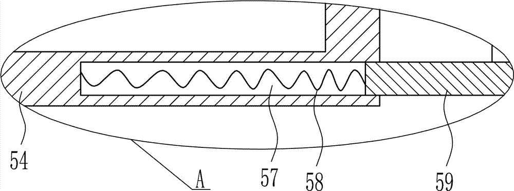
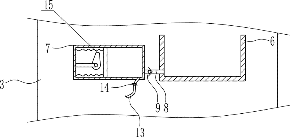
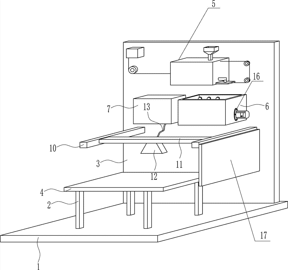
[0038] A kind of high-efficiency spraying equipment of UV paint for electronic products, such as Figure 1-10 As shown, it includes a bottom plate 1, a leg 2, a rear side plate 3, a placement plate 4, a discharge device 5, a charging box 6, a compression cylinder 7, a feed pipe 8, a first one-way valve 9, a first connection Rod 10, second connecting rod 11, nozzle 12, first discharge pipe 13, second one-way valve 14 and pushing device 15, support legs 2 are provided on the front side of the top of the bottom plate 1, vertically set on the rear side of the top of the bottom plate 1 Rear side plate 3, the rear side plate 3 is connected to the top of the bottom plate 1 by means of bolt connection, the upper part of the front side of the rear side plate 3 is provided with a discharge device 5, and the front side of the rear side plate 3 below the discharge device 5 is provided with a charging device. Box 6 and compression cylinder 7. The charging box 6 is located on the left side ...
Embodiment 2
[0040] A kind of high-efficiency spraying equipment of UV paint for electronic products, such as Figure 1-10 As shown, it includes a bottom plate 1, a leg 2, a rear side plate 3, a placement plate 4, a discharge device 5, a charging box 6, a compression cylinder 7, a feed pipe 8, a first one-way valve 9, a first connection Rod 10, second connecting rod 11, nozzle 12, first discharge pipe 13, second one-way valve 14 and pushing device 15, support legs 2 are provided on the front side of the top of the bottom plate 1, vertically set on the rear side of the top of the bottom plate 1 Rear side plate 3, the rear side plate 3 is connected to the top of the bottom plate 1 by means of bolt connection, the upper part of the front side of the rear side plate 3 is provided with a discharge device 5, and the front side of the rear side plate 3 below the discharge device 5 is provided with a charging device. Box 6 and compression cylinder 7. The charging box 6 is located on the left side ...
Embodiment 3
[0043] A kind of high-efficiency spraying equipment of UV paint for electronic products, such as Figure 1-10 As shown, it includes a bottom plate 1, a leg 2, a rear side plate 3, a placement plate 4, a discharge device 5, a charging box 6, a compression cylinder 7, a feed pipe 8, a first one-way valve 9, a first connection Rod 10, second connecting rod 11, nozzle 12, first discharge pipe 13, second one-way valve 14 and pushing device 15, support legs 2 are provided on the front side of the top of the bottom plate 1, vertically set on the rear side of the top of the bottom plate 1 Rear side plate 3, the rear side plate 3 is connected to the top of the bottom plate 1 by means of bolt connection, the upper part of the front side of the rear side plate 3 is provided with a discharge device 5, and the front side of the rear side plate 3 below the discharge device 5 is provided with a charging device. Box 6 and compression cylinder 7. The charging box 6 is located on the left side ...
PUM
 Abstract
Description
Claims
Application Information
 - R&D
- Intellectual Property
- Life Sciences
- Materials
- Tech Scout
- Unparalleled Data Quality
- Higher Quality Content
- 60% Fewer Hallucinations
Browse by: Latest US Patents, China's latest patents, Technical Efficacy Thesaurus, Application Domain, Technology Topic, Popular Technical Reports.
© 2025 PatSnap. All rights reserved.Legal|Privacy policy|Modern Slavery Act Transparency Statement|Sitemap|About US| Contact US: help@patsnap.com