Rotary wheel bracket clamp holder device and spinning machining method for large thin-wall curved face product

A processing method and wheel bracket technology, applied in the field of spinning processing, can solve the problems of long production cycle, high cost, large structure, etc., and achieve the effect of improving quality, improving production efficiency, and maintaining smooth surface finish

Inactive Publication Date: 2017-06-20
TIANJIN AEROSPACE ELECTROMECHANICAL EQUIP RES INST
View PDF5 Cites 5 Cited by
  • Summary
  • Abstract
  • Description
  • Claims
  • Application Information

AI Technical Summary

Problems solved by technology

For the forming processing of large thin-walled curved surfaces, especially the single-piece and small-batch production mode, in the production process, if the traditional spinning method is used to make concave-convex molds or molds, not only the mold molds have high precision and size requirements, but also have large structures. Special large-scale spinning machine tools are required, the cost is high, and the production cycle is long, which is a technical problem in the development and production

Method used


Image

  • Rotary wheel bracket clamp holder device and spinning machining method for large thin-wall curved face product
  • Rotary wheel bracket clamp holder device and spinning machining method for large thin-wall curved face product
  • Rotary wheel bracket clamp holder device and spinning machining method for large thin-wall curved face product

Examples


Embodiment 1

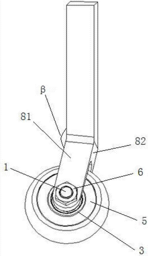
[0037] like figure 1 , 2 As shown, a wheel bracket clamping device includes a knife bar 4, a wheel seat 8 and a spinning roller 7, the knife bar 4 and the wheel seat 8 are integrally formed, and the wheel seat 8 is obliquely fixed on the side of the knife bar 4 At the end, the included angle β between the cutter bar 4 and the wheel seat 8 is an obtuse angle, and the two sides of the spinning roller 7 are clamped with a bearing seat 5, and a bearing 3 is installed in the bearing seat 5, and the spinning roller 7, bearing 3 The bearing seat 5 is arranged in the wheel seat 8, and is connected through the mandrel 1, and the mandrel 1 is locked to the wheel seat 8 by the nut 6.

[0038] A retaining ring 2 is provided between the mandrel 1 and the bearing 3 and between the nut 6 and the bearing 3 .

[0039] The side portion 81 of the wheel seat 8 and the tool bar 4 form an obtuse angle β, and the angle λ formed between the axis of the mandrel 1 and the longer side of the tool bar ...

Embodiment 2

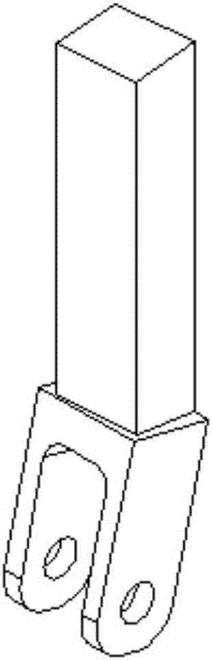
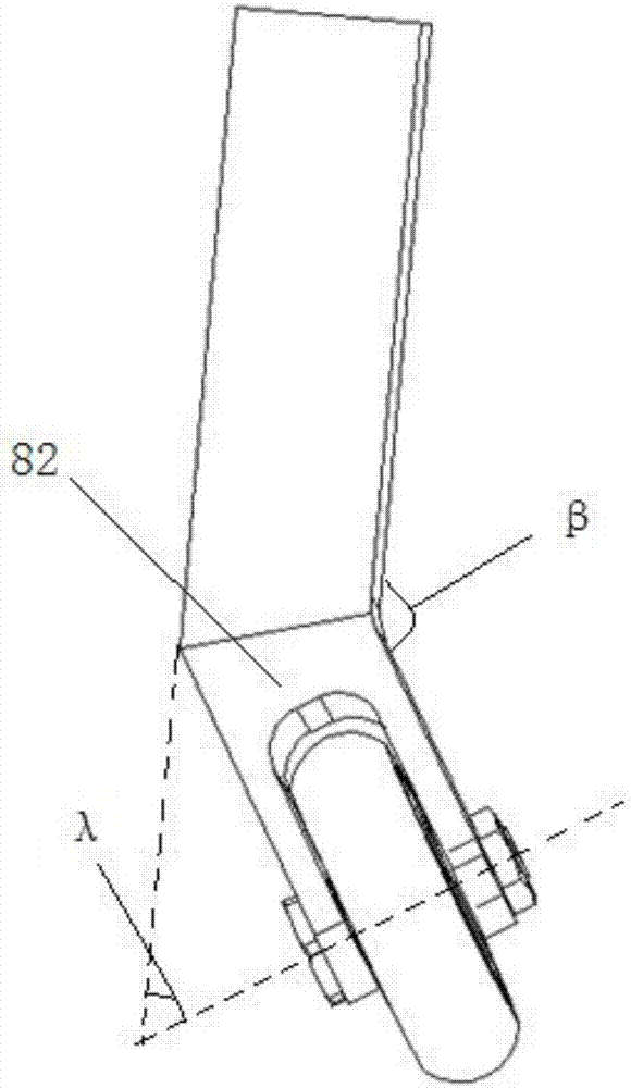
[0043] like image 3 , 4 As shown, a wheel bracket clamping device includes a knife bar 4, a wheel seat 8 and a spinning roller 7, the knife bar 4 and the wheel seat 8 are integrally formed, and the wheel seat 8 is obliquely fixed on the side of the knife bar 4 At the end, the included angle β between the cutter bar 4 and the wheel seat 8 is an obtuse angle, and the two sides of the spinning roller 7 are clamped with a bearing seat 5, and a bearing 3 is installed in the bearing seat 5, and the spinning roller 7, bearing 3 The bearing seat 5 is arranged in the wheel seat 8, and is connected through the mandrel 1, and the mandrel 1 is locked to the wheel seat 8 by the nut 6.

[0044] A retaining ring 2 is provided between the mandrel 1 and the bearing 3 and between the nut 6 and the bearing 3 .

[0045] The front part 82 of the wheel seat 8 and the cutter bar 4 form an angle β, and the axis of the mandrel 1 is perpendicular to the longer side of the cutter bar 4 .

[0046] Th...

Embodiment 3

[0053] The product to be produced is the top of a cylindrical container, which is a super-large thin-walled spherical surface with a diameter of more than 5 meters and a wall thickness of 3mm. Do. After analysis, the large thin-walled curved surface is realized by spinning on a lathe.

[0054] The rough aluminum plate needs to be fixed on the equal-diameter ring flange tooling with a certain strength. The tooling plays the role of fixing and supporting, which is convenient for downward spinning. The support tooling is designed in the shape of a ring, the material is Q235, the diameter is 5 meters, the width of the ring is 135mm, and the height is 100mm. The threaded holes are evenly distributed on the circle, so as to fasten and compress the blank aluminum plate evenly and evenly, and avoid spinning and stretching the edge. Stretch deformation and wrinkles occur.

[0055] In order to ensure good performance, 45 quenched and tempered steel is used to make the clamping handle ...


PUM

PropertyMeasurementUnit
diameteraaaaaaaaaa

Abstract

The invention provides a rotary wheel bracket clamp holder device and a spinning machining method for a large thin-wall curved face product. The rotary wheel bracket clamp holder device comprises a tool rod, a wheel base and a spinning rolling wheel which is in a three-arc combined shape. The spinning machining method for the large thin-wall curved face product comprises the steps that the periphery of a plate-shaped blank with good ductility is fixed to a tool or a die, the whole is put on a large vertical lathe platform, a spinning device is fixed to a lathe saddle, a lathe programs a curved face circular curve, rapidly spins the blank and carries out feeding machining according to an arc track in a layered circular step-by-step manner, and the blank plastically deforms under the action of the rotary wheel and forms a curved face in an accumulation manner. By means of the rotary wheel bracket clamp holder device and the spinning machining method, the product quality and the production benefits are greatly improved, it is ensured that the fracture phenomenon caused by excessive stretching cannot occur during the stretching process, the surface smoothness degree is kept, and no scratches appear on the surface.

Description

technical field [0001] The invention belongs to the technical field of spinning processing, and in particular relates to a spinning wheel bracket clamping device and a spinning processing method for large thin-walled curved surface products. Background technique [0002] The spinning process is a continuous plastic processing process with local point-by-point deformation. It has unparalleled advantages in processing thin-walled curved parts and can produce high-strength, high-performance rotary parts. It is a thin-walled hollow rotary body One of the most effective manufacturing methods for parts, it occupies a very important position in the fields of plastic processing such as aviation, automobiles, and weapons. For the forming processing of large thin-walled curved surfaces, especially the single-piece and small-batch production mode, in the production process, if the traditional spinning method is used to make concave-convex molds or molds, not only the mold molds have hi...

Claims


Application Information

Patent Timeline
Patent Type & Authority Applications(China)
IPC IPC(8): B21D22/16
CPCB21D22/16
Inventor 师占根孙建锋马建斌
Owner TIANJIN AEROSPACE ELECTROMECHANICAL EQUIP RES INST
Why Eureka
Try Eureka