Device for driving solid-liquid two-phase flow to form abrasive water jet based on electromagnetic principle

An abrasive jet, electromagnetic drive technology, used in abrasive feeding devices, abrasives, grinding/polishing equipment, etc., can solve the problems of inability to control the current on and off of the energized coil in real time, and inability to realize the collection of shunt fluids, so as to avoid electrolysis. phenomenon, avoidance of energy loss, the effect of simple structure

Active Publication Date: 2017-06-20
ANHUI UNIV OF SCI & TECH
View PDF17 Cites 6 Cited by
  • Summary
  • Abstract
  • Description
  • Claims
  • Application Information

AI Technical Summary

Problems solved by technology

[0003]However, the existing electromagnetic abrasive slurry jet device cannot form a continuous abrasive continuous jet, cannot avoid the electrolysis phenomenon in the device, and cannot effectively reduce the loss of pressure energy , which is not conducive to improving the effect of the solid-liquid two-phase flow formed by the device to form the abrasive jet pressure head. Some electromagnetic abrasive slurry jet devices cannot realize automatic pulse-type sequential control of the energized coil to drive the mainstream thick channel, the upward inclined thin channel and the downward inclined thin channel. The solid-liquid two-phase flow forms an abrasive jet, which cannot control the on-off current of the energized coil in real time, effectively avoids the use of valves and pump components, and has no seal leakage problem, and some electromagnetic abrasive slurry jet devices cannot realize upward or downward slopes. The connection between the thin channel and the main main channel where the fluids converge cannot effectively avoid the energy loss of the solid-liquid two-phase flow

Method used


Image

  • Device for driving solid-liquid two-phase flow to form abrasive water jet based on electromagnetic principle
  • Device for driving solid-liquid two-phase flow to form abrasive water jet based on electromagnetic principle
  • Device for driving solid-liquid two-phase flow to form abrasive water jet based on electromagnetic principle

Examples


Embodiment Construction

[0020] In order to make the technical means, creative features, objectives and effects achieved by the present invention easy to understand, the present invention will be further described below in conjunction with specific embodiments and illustrations.

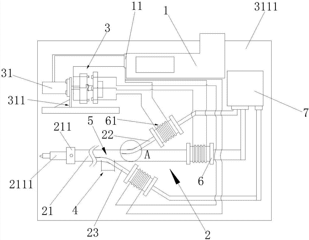
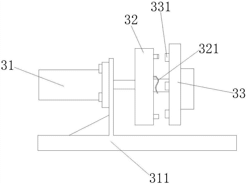
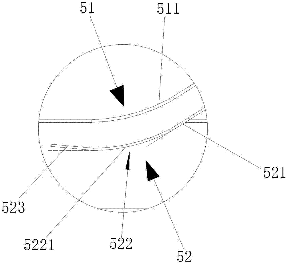
[0021] Such as figure 1 , figure 2 , image 3 , Figure 4 and Figure 5 As shown, the abrasive jet device driven by an electromagnetic mechanism to drive solid-liquid two-phase flow includes a control box 1, an electromagnetic drive device 2 and a gap on-off device 3, and the electromagnetic drive device 2 includes a main flow thick channel 21 , the upper inclined thin channel 22 and the lower inclined thin channel 23, the upper side of the main flow thick channel 21 and the lower side of the main flow thick channel 22 are provided with connecting ports 4, the upper inclined thin channel 22 and the lower inclined thin channel 23 The input port of each is provided with diversion area 5, and diversion area 5 is made up of...


PUM


Abstract

The invention discloses a device for driving solid-liquid two-phase flow to form abrasive water jet based on the electromagnetic principle. The device comprises a control box, an electromagnetic driving device and an intermittent on/off device. The electromagnetic driving device comprises a main flow coarse channel, an upper inclined and thin channel and a lower inclined and thin channel. The upper side and the lower side of the main flow coarse channel are both provided with connecting end openings. An input end opening of the upper inclined and thin channel and an input end opening of the lower inclined and thin channel are both provided with flow guide areas. Each flow guide area is composed of an upper transition arc-shaped region and a lower transition arc-shaped region. Each upper transition arc-shaped region is provided with an arc A. Each lower transition arc-shaped region is composed of an extending section, an arc-shaped transition section and an inclined section. According to the device, the function of driving the solid-liquid two-phase flow to form continuous abrasive water jet through intermittent multi-directional combination is adopted, the phenomenon of electrolysis in the device can be effectively avoided, pressure energy losses are effectively reduced, and the effect of driving the solid-liquid two-phase flow to form an abrasive water jet pressure head through the device is effectively improved.

Description

technical field [0001] The invention relates to the technical field of abrasive water jet mechanical equipment design, in particular to an abrasive jet device driven by an electromagnetic mechanism to drive solid-liquid two-phase flow. Background technique [0002] The water jet is a high-speed water stream of different shapes formed by the nozzle, and the flow rate of the jet depends on the pressure drop before and after the nozzle outlet section. Water jetting is the simplest form of energy transformation and application. Usually, the power-driven pump completes a suction and discharge process of water, pumps a certain amount of water to the high-pressure pipeline, and makes it reach the nozzle with a certain amount of energy. The hole diameter of the nozzle is required to be much smaller than that of the high-pressure pipeline, so this certain amount of water reaching the nozzle must be accelerated if it wants to flow out of the nozzle hole. In this way, the water that ...

Claims


Application Information

Patent Timeline
Patent Type & Authority Applications(China)
IPC IPC(8): B24C5/00B24C7/00
CPCB24C5/00B24C7/0007Y02P70/10
Inventor 谢淮北杜鹏王岩
Owner ANHUI UNIV OF SCI & TECH
Why Eureka
Try Eureka