Silicon wafer wire cutting machine

A technology of wire cutting machine and silicon wafer, applied in the direction of working accessories, fine working devices, stone processing equipment, etc., can solve the problems of cumbersome installation, easy chipping of silicon wafers, and easy off-line, etc., so as to improve production efficiency and improve Cutting efficiency and the effect of reducing the probability of wire breakage

Active Publication Date: 2017-06-20
无锡展照精密机械科技有限公司
View PDF5 Cites 6 Cited by
  • Summary
  • Abstract
  • Description
  • Claims
  • Application Information

AI Technical Summary

Problems solved by technology

[0002] For the cutting head of the traditional silicon wafer wire cutting equipment, the center distance of the bearing box is relatively wide, the center distance is wide, the rotation speed of the guide wheel is slow, the cutting efficiency is low, the wire is easily broken during the cutting process, the silicon wafer is easy to break, and more serious cause the entire silicon rod to break
The original mortar nozzle is directly sprayed on the silicon wafer or the wire net, and the impact force of

Method used


Image

  • Silicon wafer wire cutting machine
  • Silicon wafer wire cutting machine
  • Silicon wafer wire cutting machine

Examples


Embodiment Construction

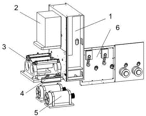
[0017] Such as figure 1 As shown, a silicon wafer wire cutting machine includes a cutting head 3, a feed table 2, a feed table fixing frame 1, a wire take-up tool 4, a wire barrel chamber 6 and a main motor 5, and the feed table 2 is fixed In the feeding table fixing frame 1, the cutting head 3 is located under the feeding table 2, and the cutting head 3 is provided with a wire take-up tooling 4 on one side, and the other side of the feeding table fixing frame 1 is provided with a wire spool chamber 6;

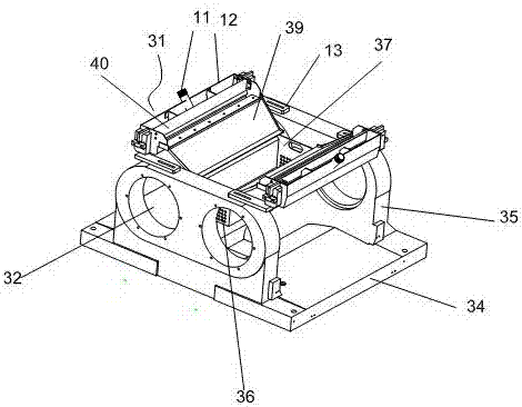
[0018] Such as figure 2 As shown, the cutting head 3 includes a cutting head base 34, a cutting head column 35 positioned at the two ends of the cutting head base 34, a mortar nozzle 31, and a debris box 37. The cutting head column 35 is provided with two The cutting head mounting hole 32 of the bearing of the head bearing box; the mortar nozzle 31 is located in the middle of the cutting head column 35, one on each side, opposite to each other; between the two mortar nozzle...


PUM


Abstract

The invention discloses a silicon wafer wire cutting machine which comprises a cutting head, a feeding table, a feeding table fixing frame, a wire winding and unwinding tool, a wire drum chamber and a main motor. The feeding table is fixed to the feeding table fixing frame. The cutting head is located below the feeding table. The wire winding and unwinding tool is arranged on one side of the cutting head, and a wire drum chamber is arranged on the other side of the feeding table fixing frame. Mortar nozzles are arranged on the two sides of a cutting guiding wheel, after boxes are fully filled with mortar, the mortar flows out at a constant speed, impact force on the silicon wafer is small, and the mortar on the two sides can be evenly distributed on a wire net. According to the cutting head of the silicon wafer wire cutting machine, the central distance between mounting holes is smaller, the wire net is smaller, stability is higher, wires are not prone to breaking, cutting quality is higher, and production efficiency and the silicon wafer percent of pass are increased.

Description

technical field [0001] The invention belongs to the technical field of silicon wafer wire cutting, in particular to a silicon wafer wire cutting machine. Background technique [0002] For the cutting head of the traditional silicon wafer wire cutting equipment, the center distance of the bearing box is relatively wide, the center distance is wide, the rotation speed of the guide wheel is slow, the cutting efficiency is low, the wire is easily broken during the cutting process, the silicon wafer is easy to break, and more serious Cause the entire silicon rod to break. The original mortar nozzle is directly sprayed on the silicon wafer or the wire net, and the impact force of the mortar on the silicon wafer is relatively large, which may easily cause the silicon wafer to break, and the mortar cannot be evenly distributed on the wire net; in addition, the traditional mortar nozzle is used in a large number, and the installation is cumbersome . [0003] There are two guide w...

Claims


Application Information

Patent Timeline
IPC IPC(8): B28D5/04B28D7/00
Inventor 李磊
Owner 无锡展照精密机械科技有限公司
Why Eureka
Try Eureka