Hierarchical water storage gate
A technology of gates and water wheels, applied in the field of water conservancy applications, can solve problems such as energy waste and damage
- Summary
- Abstract
- Description
- Claims
- Application Information
AI Technical Summary
Problems solved by technology
Method used
Image

Examples
Embodiment 1
[0029] like Figure 1-5 shown.
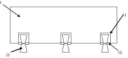
[0030] A graded water storage gate includes a gate body, a power generation device and a fishing device.
[0031] The gate body is provided with a plurality of gate notches on the lower side.
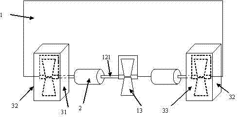
[0032] The power generation device includes a water wheel device and a generator set, the water wheel device includes a water wheel shaft, water wheel blades and a transmission shaft, the water wheel shaft is installed transversely at the middle and lower part of the gate gap, and the water wheel blades are installed On the water wheel shaft, one end of the transmission shaft is coaxially installed with the water wheel shaft, and the other end is coaxially installed with the input shaft of the generator set.
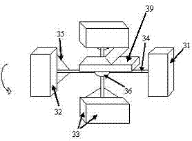
[0033] There are 4 fishing devices, all of which are arranged on the backwater side of the gate body, including a fishing box, a rotating device and a fish storage box. The side where the support rod is connected with the rotating shaft of the r...
Embodiment 2
[0041] A graded water storage gate includes a gate body, a power generation device and a fishing device.
[0042] The gate body is provided with a plurality of gate notches on the lower side.
[0043] The power generation device includes a water wheel device and a generator set, the water wheel device includes a water wheel shaft, water wheel blades and a transmission shaft, the water wheel shaft is installed transversely at the middle and lower part of the gate gap, and the water wheel blades are installed On the water wheel shaft, one end of the transmission shaft is coaxially installed with the water wheel shaft, and the other end is coaxially installed with the input shaft of the generator set.
[0044] There are 8 fishing devices, all of which are arranged on the backwater side of the gate body, including a fishing box, a rotating device and a fish storage box. The side where the support rod is connected with the rotating shaft of the rotating device is the release surfa...
Embodiment 3
[0052] like Figure 1-Figure 6 as shown, image 3 for figure 2 Schematic diagram of the overall fishing device structure of the fishing box on the left in the middle, figure 2 The fishing box on the right also has the same overall fishing device, the difference is that it rotates in the opposite direction, and the installation position of the spherical snap joint on the release surface is the same as that of the image 3 In contrast, it can ensure that when turning, the direction of the fish-entry surface is opposite to the flow direction of the vortex, and then the fish-entry surface will rotate upwards. When the fishing box rotates to the fixed point (the highest point), the release surface of the lower part will use One side is the shaft and the other side is opened due to the gravity of the card joint (mainly due to the cooperation between the gravity of the card joint itself and the card connection strength of the card interface. When there are fish in the fishing box...
PUM
 Abstract
Description
Claims
Application Information
 - R&D
- Intellectual Property
- Life Sciences
- Materials
- Tech Scout
- Unparalleled Data Quality
- Higher Quality Content
- 60% Fewer Hallucinations
Browse by: Latest US Patents, China's latest patents, Technical Efficacy Thesaurus, Application Domain, Technology Topic, Popular Technical Reports.
© 2025 PatSnap. All rights reserved.Legal|Privacy policy|Modern Slavery Act Transparency Statement|Sitemap|About US| Contact US: help@patsnap.com