
Structural steel-steel car combined structure, manufacturing method and structural steel concrete structure

A technology of concrete structure and composite structure, which is applied in the direction of building structure and construction, and can solve the problems of difficult construction, more holes in the web of section steel, and affecting the overall strength of section steel, etc.

Pending Publication Date: 2017-06-20
SHENZHEN GENERAL INST OF ARCHITECTURAL DESIGN & RES
View PDF5 Cites 8 Cited by
  • Summary
  • Abstract
  • Description
  • Claims
  • Application Information

AI Technical Summary

Problems solved by technology

[0004] The technical problem to be solved by the present invention is to provide a steel-reinforced combined structure and manufacturing method, steel concrete structure and construction method, so as to avoid the need to open more holes in the steel web in the existing steel concrete structure and affect the overall strength of the steel , difficulty in construction, etc.

Method used


Image

  • Structural steel-steel car combined structure, manufacturing method and structural steel concrete structure
  • Structural steel-steel car combined structure, manufacturing method and structural steel concrete structure
  • Structural steel-steel car combined structure, manufacturing method and structural steel concrete structure

Examples


Embodiment 1

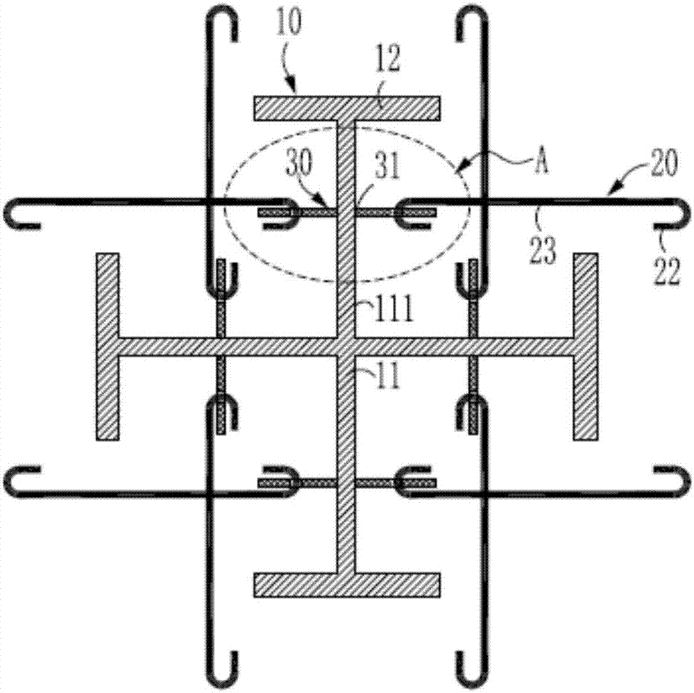
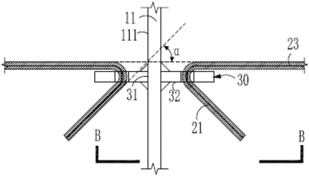
[0101] This embodiment provides a composite structure of section steel-reinforcing bar, such as figure 2 , image 3 As shown, it includes section steel 10, several tie bars 20 and several connecting pieces. Wherein, the shaped steel 10 includes a web 11 , and flange plates 12 located at both ends of the web 11 and perpendicular to the web 11 . One side of the connector is fixedly connected to the web 11 , the first end 21 of the tie bar 20 is fixedly connected to the connector, and the second end 22 opposite to the first end 21 is a free end. In this embodiment, the connecting piece is fixed on the web of the shaped steel 10, so that the tie bars can be directly connected with the connecting piece, instead of passing through the web after perforating the web. This can avoid opening holes on the web plate due to the setting of tie bars, avoid reducing the overall strength of the section steel, and secondly make the opening operation easier for construction, improve construct...

Embodiment 2

[0115] This embodiment provides a composite structure of section steel-reinforcing bar, such as Image 6 , Figure 7 As shown, it includes section steel 10, several tie bars 20 and several connecting pieces. Wherein, the shaped steel 10 includes a web 11 , and flange plates 12 located at both ends of the web 11 and perpendicular to the web 11 . One side of the connector is fixedly connected to the web 11 , the first end 21 of the tie bar 20 is fixedly connected to the connector, and the second end 22 opposite to the first end 21 is a free end. In this embodiment, the connecting piece is fixed on the web of the shaped steel 10, so that the tie bars can be directly connected with the connecting piece, instead of passing through the web after perforating the web. This can avoid opening holes on the web plate due to the setting of tie bars, avoid reducing the overall strength of the section steel, and secondly make the opening operation easier for construction, improve construct...

Embodiment 3

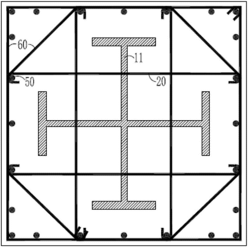
[0127] This embodiment provides a steel concrete structure, such as Figure 11 to Figure 13 As shown, it includes section steel 10, some tie bars 20, some connectors, some longitudinal bars 50, some stirrups 60 and concrete 70, wherein:

[0128] Shaped steel 10 is a cross-shaped steel, including web 11 and flange plate 12, and this flange plate 12 is positioned at the two ends of web 11 and intersects perpendicularly with web 11; Figure 11 The direction perpendicular to the paper surface) is arranged around the section steel, and the longitudinal bars 50 are arranged at intervals; the stirrups 60 are closed and enclosed outside the longitudinal bars 50 along the direction perpendicular to the length of the longitudinal bars 50, and are fixed to the longitudinal bars 50 Form the outer boundary of the above-mentioned shaped steel concrete structure; one side of the connector is fixedly connected to the plane 111 of the web 11, the first end 21 of the tie bar 20 is fixedly conne...


PUM


Abstract

The invention relates to the field of building structures, in particular to a structural steel-steel bar combined structure, a manufacturing method and a structural steel concrete structure. The structural steel-steel bar combined structure comprises structural steel, a plurality of tie bars and a plurality of connecting pieces. The structural steel comprises webs and frange plates which are located at the two ends of the webs and perpendicularly intersect with the webs. One side of each connecting piece is fixedly connected with the corresponding web. The first end of each tie bar is fixedly connected to the corresponding connecting piece, and a second end opposite to the first end is a free end. According to the structural steel-steel bar combined structure, the manufacturing method and the structural steel concrete structure, the connecting pieces used for fixing the tie bars are specially arranged in the positions, corresponding to the tie bars, of the two sides of the structural steel webs, thus, no hole needs to be drilled in the structural steel webs, the effect that the overall structure of the structural steel is not damaged is guaranteed, and accordingly the overall strength of the structural steel concrete structure is guaranteed.

Description

technical field [0001] The invention relates to the field of building structures, in particular to a steel-steel combined structure and a manufacturing method thereof, a steel concrete structure with the combined structure and a construction method thereof. Background technique [0002] The reinforced concrete structure is a structure composed of embedded steel inside the reinforced concrete. Due to the addition of section steel in reinforced concrete, compared with traditional reinforced concrete structures, section steel concrete structures have the advantages of large bearing capacity, high rigidity, and good earthquake resistance. [0003] When considering the seismic effect, closed stirrups should be used for the steel concrete frame columns and frame pillars, and as many longitudinal bars as possible should be restrained by stirrups and / or tie bars in different directions. When tie bars are used, the tie bars should be close to the longitudinal bars and hook the close...

Claims


Application Information

Patent Timeline
Patent Type & Authority Applications(China)
IPC IPC(8): E04B1/30
CPCE04B1/185E04B1/30
Inventor 梁艳
Owner SHENZHEN GENERAL INST OF ARCHITECTURAL DESIGN & RES
Learn More