
Fully-fabricated steel-prefabricated concrete floor slab composite beam

A prefabricated concrete, fully assembled technology, applied in the direction of floors, buildings, building components, etc., can solve the problems of increasing costs, more formwork and on-site supports, reducing construction efficiency, etc., and achieves reasonable self-balancing force performance and easy operation of construction procedures. , the effect of shortening the construction period

Pending Publication Date: 2017-06-20
SHANDONG UNIV
View PDF15 Cites 1 Cited by
  • Summary
  • Abstract
  • Description
  • Claims
  • Application Information

AI Technical Summary

Problems solved by technology

However, there are the following disadvantages: ①The amount of wet work is very large, resulting in low construction efficiency, high cost and environmental pollution; ②There are too many formwork and on-site supports, which further reduces the construction efficiency and increases the cost; ③Steel beams and cast-in-place concrete floors are pouring After that, it is integrated and cannot be disassembled. As a result, when the load of the floor of the existing structure increases, the thick floor cannot be replaced. When the floor is damaged, the new floor cannot be replaced, and the floor cannot be recycled, which is not suitable for building industrialization
However, there are still deficiencies, which are mainly manifested in: ①Concrete still needs to be poured on site to realize the combination effect, and there are many wet operations, resulting in low construction efficiency, high cost and environmental pollution; When the span is large, support is required, and the bottom of the slab needs to be treated for fire protection and anticorrosion, which is costly; when the span of prestressed concrete composite slab (slab) and reinforced truss concrete composite slab is greater than 1.8m, support is required, and ribbed Stressed concrete laminated slabs need to be supported when the span is greater than 3.6m, which further reduces construction efficiency and increases costs; When the floor load increases, the thick floor cannot be replaced, and when the floor is damaged, the new floor cannot be replaced, and the floor cannot be recycled, which is not suitable for building industrialization

Method used


Image

  • Fully-fabricated steel-prefabricated concrete floor slab composite beam
  • Fully-fabricated steel-prefabricated concrete floor slab composite beam
  • Fully-fabricated steel-prefabricated concrete floor slab composite beam

Examples


Embodiment 1

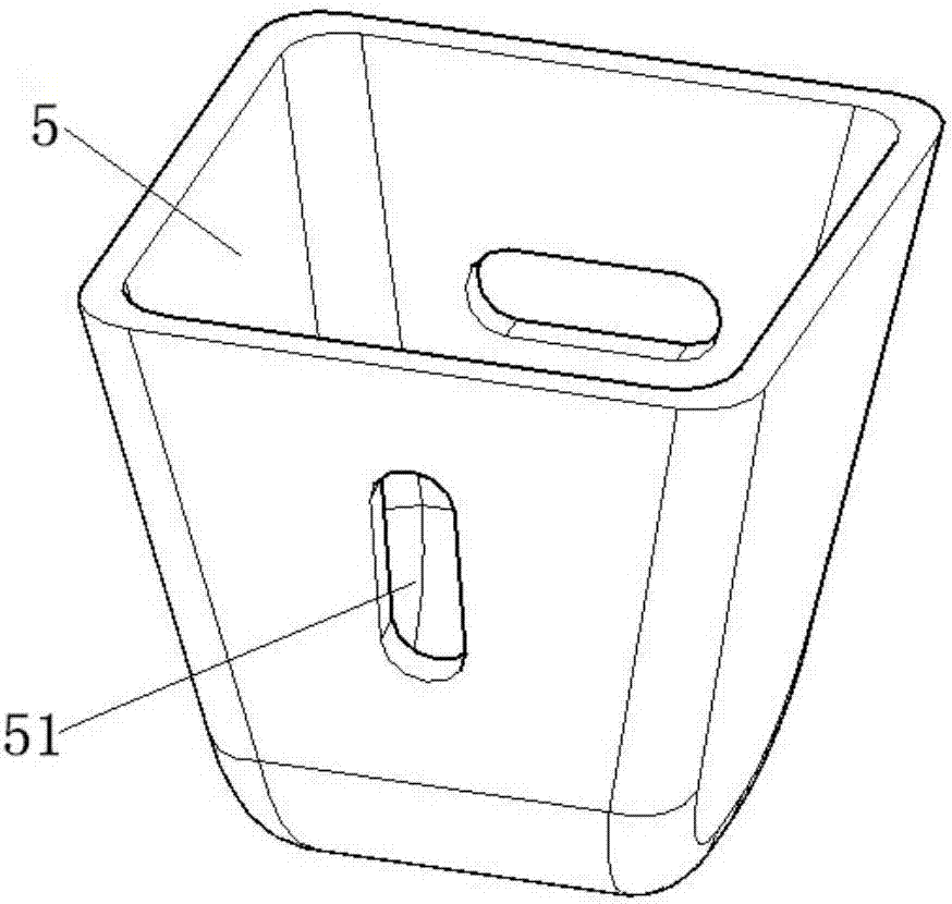
[0064] In embodiment 1, such as image 3 As shown, the bottom of the connecting member 5 is a bowl-shaped structure, the top is a square structure and the top is open, and a pair of opposite side walls of the connecting member 5 are provided with a first through hole 51 corresponding to the inner wire sleeve 22 .

Embodiment 2

[0065] In embodiment 2, such as Figure 4 with Figure 5 As shown, the connecting member 5 is a square steel pipe, and a pair of opposite side walls of the square steel pipe are provided with a first through hole 51 corresponding to the inner wire sleeve 22 .

[0066] In Embodiment 1, when the connecting member 5 of the present invention adopts a bowl-shaped structure at the bottom, a square structure at the top and an open top, when the connecting member 5 is subjected to external effects, the bowl-shaped structure at the bottom can avoid stress concentration. The first through hole on the side wall of the connecting member 5 is used to connect two adjacent prefabricated concrete floor slabs 2 through bolts. The connection member 5 of the present invention has low manufacturing cost, high connection quality and effect, and can be reused many times.

[0067] In embodiment 2, when the connecting member 5 of the present invention adopts the structural form of a square steel p...

Embodiment 3

[0093] Embodiment 3: as Figure 17 with Figure 18 As shown, the end of the precast concrete floor 2 is provided with a groove 24 that is not connected to the top, and the limiting claw 63 is set in the groove 24 .

[0094] In Embodiment 1 and Embodiment 2, the position corresponding to the through hole 66 on the stop claw 63 on the precast concrete floor 2 can be pre-embedded with an inner wire sleeve, so that the end stop member 6 can be connected with the precast concrete floor 2 bolt connection.

[0095] In Embodiment 2 and Embodiment 3, the limiting pawl 63 can not only limit the up and down movement of the precast concrete floor 2 relative to the steel beam 1 , but also limit the left and right movement of the precast concrete floor 2 relative to the steel beam 1 .

[0096] In the present invention, steel girder 2 and steel girder 1 can have multiple structural forms, as can be T-shaped steel girder, comprise upper flange and web; Web and lower flange; it can also be ...


PUM


Abstract

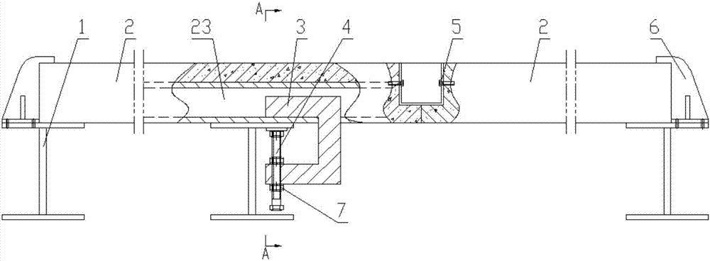
The invention discloses a fully fabricated steel-prefabricated concrete floor slab composite beam and relates to the field of architectural structure. The composite beam comprises a steel beam with an upper flange, a plurality of prefabricated concrete floor slabs combined with one another in the same plane and pre-embedded with guide grooves, connecting members, a C-shaped clamping member, a fastener and an end stop member; the prefabricated concrete floor slabs are mounted on the upper surface of the upper flange of the steel beam, a plurality of opening grooves matched with the connecting members are formed in the side walls of prefabricated concrete floor slabs, and the prefabricated concrete floor slabs are fixed to the upper surface of the upper flange of the steel beam through the C-shaped clamping member and the fastener; and the end stop member comprises a bottom plate used for being connected with the upper flange of the steel beam in a bolted mode, a stop plate is arranged on the bottom plate, and the ends of the prefabricated concrete floor slabs are placed between the stop plate and the upper flange of the steel beam. The fully-fabricated steel-prefabricated concrete floor slab composite beam is capable of avoiding wet operation in the construction process, simple in structure, convenient to dismount and mount, high in construction efficiency, and capable of realizing replacement and recycling of the prefabricated concrete floor slabs.

Description

technical field [0001] The invention relates to the field of building structures, in particular to a fully assembled steel-prefabricated concrete floor composite beam. Background technique [0002] Steel-concrete composite beam is a new type of structure developed on the basis of steel structure and concrete structure. It mainly resists the lifting and relative slippage at the interface between the steel beam and the concrete floor by setting shear connectors (bolts, channel steel, bending bars, etc.), making them work together as a whole . [0003] At present, the commonly used steel-concrete composite beams are steel-cast-in-place concrete floor composite beams and steel-laminated monolithic concrete floor composite beams. [0004] The steel-cast-in-place concrete floor composite beam is composed of a steel beam, a cast-in-place concrete floor and shear studs. It has the advantages of high overall rigidity and significant combination effect, and is suitable for floors wi...

Claims


Application Information

Patent Timeline
IPC IPC(8): E04B5/10
CPCE04B5/10
Inventor 曲冰程积润侯和涛刘锦伟邱灿星罗建良
Owner SHANDONG UNIV
Learn More