Eureka AIR delivers breakthrough ideas for toughest innovation challenges, trusted by R&D personnel around the world.

Sunlight tracking and reflecting device

A reflective device and solar light technology, applied in the field of solar power generation, can solve the problems of reduced tracking accuracy, damage to the heat collector, unfavorable driving angle for snow removal and heliostat rotation protection, etc., and achieve the effect of improving control accuracy and reliability

Active Publication Date: 2017-06-20
深圳中科能投能源有限公司
View PDF6 Cites 8 Cited by
  • Summary
  • Abstract
  • Description
  • Claims
  • Application Information

AI Technical Summary

Problems solved by technology

[0004] The open-loop control structure of the existing tower-type heliostat is simple and easy to implement, but because this method cannot eliminate the mechanical deviation of the tracking system and will generate cumulative errors during continuous tracking, the tracking accuracy is not high, and with the working time of the heliostat The longer the mechanical wear will lead to the continuous reduction of tracking accuracy
Due to the low tracking accuracy of the heliostat, it is impossible to accurately control the projected position of the focused spot of the heliostat on the collector, so that the energy density distribution on the collector cannot be precisely controlled, which increases the difficulty of collector control and causes collector The local temperature of the heat collector is too high to damage the heat collector or the local temperature of the heat collector is too low to cause the internal working medium to freeze, etc.
The existing tower-type heliostat pitch angle shaft is generally driven by a single push rod. The limited driving angle is not conducive to snow removal during snowfall and the heliostat rotates to a specific angle for protection during strong winds.

Method used


Image

  • Sunlight tracking and reflecting device
  • Sunlight tracking and reflecting device
  • Sunlight tracking and reflecting device

Examples


Embodiment 1

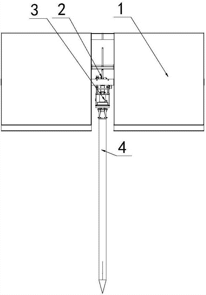
[0028] The invention provides a solar ray tracing reflection device, such as Figure 1-5 As shown, it includes: a mirror assembly 1, a pitch drive assembly 2, an azimuth drive assembly 3 and a column assembly 4, the pitch drive assembly 2 is respectively connected to the mirror assembly 1 and the azimuth drive assembly 3, and the column assembly 4 passes through the flange Rotatably connected below the azimuth drive assembly 3, the mirror assembly 1 rotates in a vertical plane driven by the pitch drive assembly 2, and the mirror assembly 1 rotates in the azimuth drive assembly 3 Under the action of rotating in the horizontal plane, the pitch drive assembly 2 pushes the mirror assembly 1 to rotate within a vertical range of 180° through a double push rod structure, which is convenient for mirror control and snow cleaning.

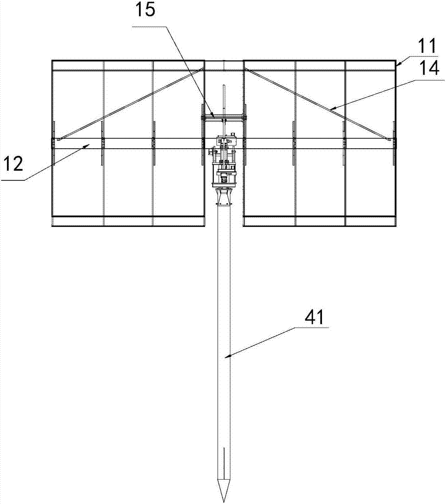
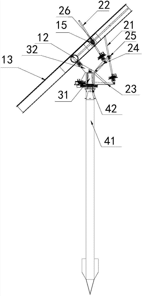
[0029] The reflector assembly 1 includes a reflector frame 11 and at least one reflector 13 installed in the reflector frame 11, the reflector frame 11 is h...


PUM


Abstract

The invention relates to the technical field of solar power generation, and particularly relates to a sunlight tracking and reflecting device. The sunlight tracking and reflecting device comprises a reflecting mirror assembly, a pitch driving assembly, an azimuth driving assembly and a vertical column assembly, and is characterized in that the pitch driving assembly is respectively connected with the reflecting mirror assembly and the azimuth driving assembly, the vertical column assembly is rotatably connected below the azimuth driving assembly, the pitch driving assembly comprises a first push rod and a second push rod which are respectively hinged on a first hinging base and a second hinging base, the first push rod is movably connected on the first hinging base, the top end of the second push rod is connected with the reflecting mirror assembly, and the reflecting mirror assembly rotates within a vertical 180-degree range through linkage of the first push rod and the second push rod. The reflecting mirror assembly is driven to rotate within the vertical 180-degree range through the pitch driving assembly with a double-push-rod structure, so that operations such as reflecting mirror control and accumulated snow cleaning are facilitated.

Description

technical field [0001] The invention relates to the technical field of solar power generation, in particular to a solar ray tracing reflection device. Background technique [0002] The tower solar thermal power station is a concentrated solar thermal power generation system. The tower system is to build a heat collection tower on the ground, install a heat collector on the top of the tower, and install a certain number of heliostats around the heat collection tower. The working medium in the heater generates high-temperature steam, which drives the steam turbine to generate electricity. [0003] A large number of heliostats around the heat collection tower constitute a mirror field, and the mirror field control system controls each heliostat in the mirror field to make the focused solar spot projected to the target position of the heat collector. During the operation of the sun, its altitude angle and azimuth angle change continuously with time. To make the focused spot of...

Claims


Application Information

Patent Timeline
Patent Type & Authority Applications(China)
IPC IPC(8): G05D3/12
CPCG05D3/12
Inventor 孙海翔赵晓东滕广平夏越
Owner 深圳中科能投能源有限公司
Why Eureka
Eureka Blog
Learn More