
Thermoelectric Module

A thermoelectric module and thermoelectric technology, applied to thermoelectric device components, thermoelectric devices that only use the Peltier or Seebeck effect, etc., can solve problems such as high output voltage, achieve large output voltage, and improve module efficiency.

Active Publication Date: 2019-04-23
廖建能
View PDF5 Cites 0 Cited by
  • Summary
  • Abstract
  • Description
  • Claims
  • Application Information

AI Technical Summary

Problems solved by technology

[0003] However, conventional thermoelectric modules only generate an electric field parallel to the direction of temperature difference, and it is difficult to adjust the thermoelectric performance of the module by changing the size of the P-type and N-type thermoelectric components in the module. Therefore, a large number of P-type and N-type thermoelectric materials need to be connected in series In order to obtain a higher output voltage under a fixed temperature difference

Method used


Image

  • Thermoelectric Module
  • Thermoelectric Module
  • Thermoelectric Module

Examples


Embodiment Construction

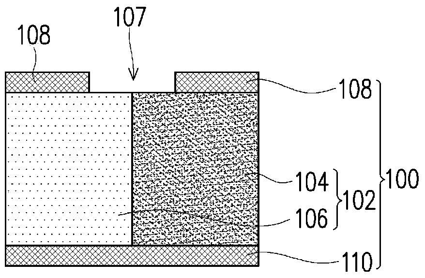
[0044] figure 1 It is a schematic diagram of the thermoelectric module of the first embodiment of the present invention.

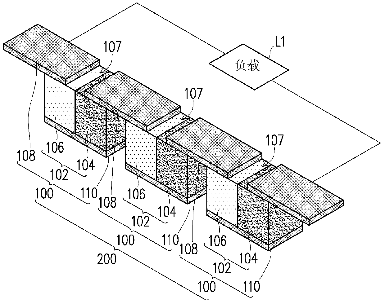
[0045] Please refer to figure 1 , the thermoelectric module includes at least one PN junction element 100 . In this embodiment, the thermoelectric module is described by including one PN junction element 100 as an example, that is, one PN junction element 100 can be used as the smallest unit of the thermoelectric module, but the present invention is not limited thereto. In other embodiments, the thermoelectric module may also include a plurality of PN junction elements 100 .

[0046] A PN junction device 100 includes a PN junction structure 102 , a plurality of upper electrodes 108 and at least one lower electrode 110 . In the first embodiment, a PN junction element 100 including a lower electrode 110 is taken as an example for illustration, but the present invention is not limited thereto. In other embodiments, a PN junction device 100 may also includ...


PUM


Abstract

The invention provides a thermoelectric module, which includes at least one PN junction element. The PN junction element includes a PN junction structure, a plurality of upper electrodes and at least a lower electrode. The PN junction structure includes an N-type thermoelectric component and a P-type thermoelectric component, wherein the N-type thermoelectric component and the P-type thermoelectric component are connected on opposite sides. The upper electrodes are separated from each other and respectively cover part of the upper surface of the N-type thermoelectric component or part of the upper surface of the P-type thermoelectric component. The lower electrode covers the lower surface of the N-type thermoelectric component and the lower surface of the P-type thermoelectric component. The thermoelectric module provided by the invention can effectively improve the efficiency of the module.

Description

technical field [0001] The invention relates to a thermoelectric module, in particular to a thermoelectric module with lateral output voltage. Background technique [0002] Many industries need to consume a lot of energy and generate considerable heat in the manufacturing process, resulting in a lot of energy waste. Generally, thermoelectric modules can use temperature difference to generate electricity. The advantages are that they take up little space and have low maintenance costs. Therefore, they are suitable for recovering industrial waste heat to avoid energy waste. [0003] However, conventional thermoelectric modules only generate an electric field parallel to the direction of temperature difference, and it is difficult to adjust the thermoelectric performance of the module by changing the size of the P-type and N-type thermoelectric components in the module. Therefore, a large number of P-type and N-type thermoelectric materials need to be connected in series Only ...

Claims


Application Information

Patent Timeline
Patent Type & Authority Patents(China)
IPC IPC(8): H01L35/10H01L35/32H10N10/82H10N10/17
CPCH10N10/82H10N10/17
Inventor 廖建能卢孟珮戴明吉陈力祺黄泓宪
Owner 廖建能
Learn More