Contactless Connector System Having Feedback From Secondary Side

A non-contact, connector technology, applied in transmission systems, near-field transmission systems, electrical components, etc., to achieve simple control algorithms, reliable on and off, and improved foreign object detection

Inactive Publication Date: 2017-06-20
TYCO ELECTRONICS NETHERLAND BV +1
View PDF11 Cites 6 Cited by
  • Summary
  • Abstract
  • Description
  • Claims
  • Application Information

AI Technical Summary

Problems solved by technology

[0011] However, known contactless connector systems that transfer both power and data use resonant drive circuits to transfer power in an efficient manner, and these resonant systems are controlled based on feed-forward control, which means that there is no measurement and The information sent can be used to control

Method used


Image

  • Contactless Connector System Having Feedback From Secondary Side
  • Contactless Connector System Having Feedback From Secondary Side
  • Contactless Connector System Having Feedback From Secondary Side

Examples


Embodiment Construction

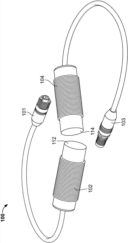
[0062] The invention will now be explained in more detail with reference to the accompanying drawings, first with reference to figure 2 . figure 2 A perspective view of a contactless connector system 100 according to a possible embodiment of the invention is shown. The contactless connector system 100 includes a power transmitting connector 102 which can be connected to a power source (not shown in the figure) via a first terminal 101 . The power transmitting connector 102 defines the primary side of the contactless connector system 100 . The contactless connector system 100 also includes a power receiving connector 104 that defines the secondary side of the contactless connector system 100 . A second terminal 103 is provided for connecting the system to secondary side external components (not shown in the figure).

[0063] When the mating surfaces 112, 114 of the power transmitting connector 102 and the power receiving connector 104 are sufficiently close to each other, ...


PUM


Abstract

The present invention relates to a contactless connector system having a power transmitting connector (102) has a primary sided inductive coupling element (L p ) and a resonant circuit (110) for generating a magnetic field at said primary sided inductive coupling element (L p ) from an input power. A power receiving connector (104) that is mateable with said power transmitting connector (102) has a secondary sided inductive coupling element (L s ) that is operable to receive electric power when being electromagnetically coupled with said primary sided inductive coupling element (L p ). A bi-directional data link is formed between said transmitting and receiving connectors (102, 104). A secondary sided sensing unit (136) is operable to measure at least one secondary sided operational parameter, and the operation of said resonant circuit (110) is controlled in response to a combination of said at least one secondary sided operational parameter and at least one primary sided operational parameter.

Description

technical field [0001] The present invention relates to a contactless connector system and a method of controlling a contactless connector system for inductively transferring power between a power transmitting connector and a power receiving connector. Background technique [0002] The principle of inductive energy transfer is used in many applications as the physical basis for the technological development of a large number of applications. In the case of inductive energy transfer, its basic element is a loosely coupled conductor, which represents the magnetic coupling of the inductor or magnetic winding in the primary-side power transmitting device to the inductor or magnetic winding in the target device. During operation, energy is transferred inductively between the primary side portion and the secondary side portion. If the secondary side part is removed from the primary side part, the energy transfer is interrupted. In this context, the term "contactless" is used to ...

Claims


Application Information

Patent Timeline
Patent Type & Authority Applications(China)
IPC IPC(8): H02J50/12H04B5/00
CPCH04B5/0037H04B5/0075H02J50/90H02J50/12H02J50/60H02J50/80
Inventor G.哈布拉肯J.迪特纳B.曼格R.霍斯萨伊尼S.阿布尔卡塞姆F.兰格
Owner TYCO ELECTRONICS NETHERLAND BV
Why Eureka
Try Eureka