Three-level rectifier static coordinate system control method

A static coordinate system, three-level rectification technology, applied in electrical components, high-efficiency power electronic conversion, AC network to reduce harmonics/ripples, etc. The effect of suppressing harmonic components

Inactive Publication Date: 2017-06-20
邢筱丹
View PDF0 Cites 2 Cited by
  • Summary
  • Abstract
  • Description
  • Claims
  • Application Information

AI Technical Summary

Problems solved by technology

[0003] In order to overcome the problem of performance degradation of the three-level rectifier when the grid voltage is unbalanced, the present invention proposes a static coordinate system control method for the three-level rectifier

Method used


Image

  • Three-level rectifier static coordinate system control method
  • Three-level rectifier static coordinate system control method
  • Three-level rectifier static coordinate system control method

Examples


Embodiment Construction

[0016] specific implementation plan

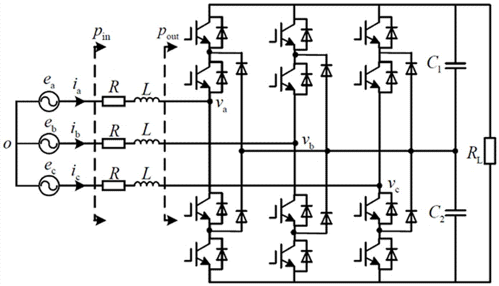
[0017] figure 1 where, is the AC side voltage of the rectifier; and R\* MERGEFORMAT are the filter inductance and equivalent series resistance of each phase respectively; C1 and C2 are the DC voltage dividing capacitors; RL is the load of the rectifier; PIN and PIN represent the grid input and the rectifier respectively instantaneous power at the terminal. The DC and AC components of the instantaneous active power at the grid input can be represented by instantaneous and delayed quantities. In the same way, the DC component and ripple component of the instantaneous reactive power QIN at the grid input terminal and the active power POUT at the rectifier terminal in a steady state can be calculated.

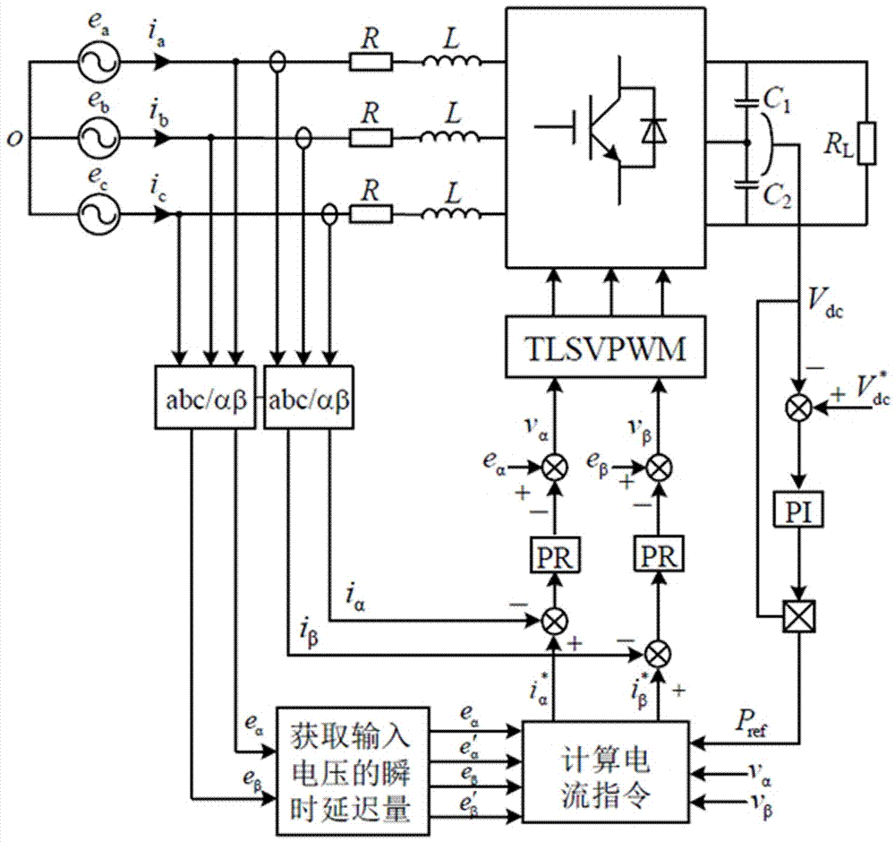
[0018] The control algorithm adopted in the present invention is realized in the static coordinate system, so no rotation transformation is required, and no positive and negative sequence components need to be calculated at the same time. f...


PUM


Abstract

The present invention discloses a three-level rectifier static coordinate system control method. The method comprises four parts consisting of a three-level PWM rectifier main circuit, static coordinate system control, a band-pass filter and a proportion resonant (PR) controller. An outer ring is a voltage ring, a traditional PI (proportional-integral) controller is employed, an inner ring is a current ring, a current instruction value is calculated based on the static coordinate system, and the PR controller is employed. The scheme does not need to perform rotation conversion and phase detection of the power grid voltage and is simple to control. the PR control system including harmonic suppression is employed to effectively inhibit the harmonic component of current at an alternating current side. The three-level rectifier static coordinate system control method realizes stable direct current voltage output and current sine input of the three-level rectifier when the power grid voltage generates single-phase dropping and there is harmonic wave.

Description

technical field [0001] The invention relates to a three-level rectifier, in particular to a method for controlling a static coordinate system of a three-level rectifier. Background technique [0002] Now there are many studies on the control algorithm of three-level rectifiers, but most of these methods are based on the condition of grid voltage balance. In the actual power grid, unbalanced loads and asymmetrical faults such as single-phase and two-phase-to-ground short-circuits will cause grid voltage asymmetry. Under the condition of unbalanced grid voltage, if the traditional grid voltage balance control strategy is used to control the pulse width modulation (PWM) rectifier, the system will appear in an abnormal operating state. When the grid voltage is unbalanced, the conventional rectifier control method is based on the theory of symmetrical components, which divides the unbalanced voltage into positive and negative sequence components for separate control. Commonly u...

Claims


Application Information

Patent Timeline
Patent Type & Authority Applications(China)
IPC IPC(8): H02M7/219H02J3/01
CPCH02J3/01H02M7/219Y02B70/10Y02E40/40
Inventor 邢筱丹
Owner 邢筱丹
Why Eureka
Try Eureka