Underwater sensor network routing method for cavity sensing

A technology of underwater sensors and sensor nodes, which is applied in the direction of network topology, advanced technology, electrical components, etc., to achieve the effect of avoiding the same layer of cyclic transmission, improving the delivery rate of data packets, and prolonging the life of the network

Active Publication Date: 2017-06-20
HARBIN ENG UNIV
View PDF6 Cites 7 Cited by
  • Summary
  • Abstract
  • Description
  • Claims
  • Application Information

AI Technical Summary

Problems solved by technology

[0006] The object of the present invention is to provide an underwater sensor network routing method for hole perception that can solve the problem of "hot spots" in underwater routing protocols while ensuring balanced energy distribution and avoiding holes

Method used


Image

  • Underwater sensor network routing method for cavity sensing
  • Underwater sensor network routing method for cavity sensing
  • Underwater sensor network routing method for cavity sensing

Examples


Embodiment Construction

[0018] The present invention will be described in more detail below with examples in conjunction with the accompanying drawings.

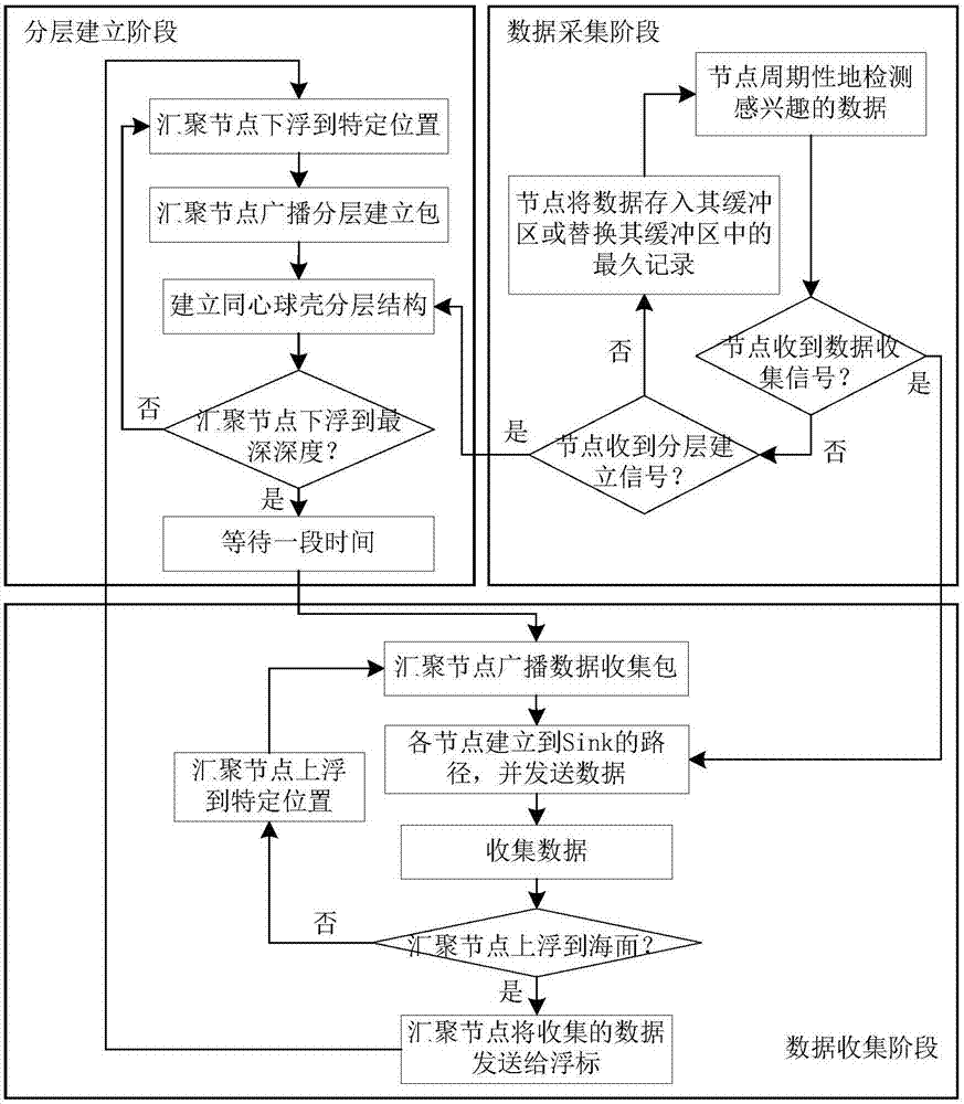
[0019] combine figure 1 , the routing method of the present invention is as follows:

[0020] When the aggregation node reaches a specific position during the floating process, it broadcasts the layered establishment packet to execute the layered establishment task; when it descends to the deepest depth, it broadcasts the layered establishment packet to execute the layered establishment task, and after waiting for a period of time, it broadcasts the data collection packet to execute the data collection task. After the data collection is completed, it starts to float; when it reaches a specific position during the floating process, it broadcasts the data collection package to perform the data collection task; when it floats to the surface, it sends the collected data to the buoy node. The node periodically detects the data of interest and completes...


PUM


Abstract

The present invention provides an underwater sensor network routing method for cavity sensing. The method includes the following steps that: when arriving at a set position during a downward floating process, an aggregation node broadcasts a layered establishment packet and executes a layered establishment task, when the aggregation node arrives at a largest depth, the aggregation node waits for a period of time, and then broadcasts a data collection packet and executes a data collection task, after finishing data collection, the aggregation node begins to float upwards, when the aggregation node arrives at the set position, the aggregation node broadcasts a data collection packet and executes a data collection task, when the aggregation node arrives the surface of water, the aggregation node sends the collected data to a buoy node; sensor nodes periodically collect data of interest; if the sensor nodes receive layered establishment signals, the sensor nodes enter a layered establishment stage and establish a concentric spherical shell layered structure; and if the sensor nodes receive data collection signals, the sensor nodes enter a data collection stage, the sensor nodes build paths to the aggregation node and send the data. According to the underwater sensor network routing method for cavity sensing of the invention, same-layer transmission and the residual energy of the nodes are considered, the generation of same-layer cyclic transmission, hot zones and cavities can be avoided, the arrival rate of data packets can be improved, and the service life of a network can be prolonged.

Description

technical field [0001] The invention relates to an underwater sensor network routing method, in particular to a hole-aware underwater sensor network routing method. Background technique [0002] The seabed observation system is one of the important prerequisites for human beings to explore the ocean, develop and utilize seabed resources. Its main tasks are to detect the unknown world, find seabed resources, and monitor the impact of human activities on the ocean. Underwater Sensor Networks (UWSNs) have the characteristics of high energy consumption, high latency, and low bandwidth. The difficulty of UWSNs research is routing selection. There are huge challenges in terms of stickiness and so on. [0003] Aiming at the low energy utilization rate of underwater sensor networks and dynamic changes in network topology, Gopi S et al. proposed a path-independent Energy Optimized Layered Routing Protocol (Energy Optimized Path Unaware Layered Routing Protocol, E-PULRP). The sensor...

Claims


Application Information

Patent Timeline
Patent Type & Authority Applications(China)
IPC IPC(8): H04W40/10H04W40/24H04W84/18
CPCH04W40/10H04W40/248H04W84/18Y02D30/70
Inventor 冯晓宁王卓张素苹曲文杰曲立平蔡绍滨
Owner HARBIN ENG UNIV
Why Eureka
Try Eureka