Waste heat-reusing energy-saving type spray-drying tower
A spray drying tower and drying tower technology, applied in the directions of spray evaporation, heat exchanger type, indirect heat exchanger, etc., can solve the problems of increasing heat energy consumption, unfavorable energy saving, etc., and achieve the effect of reducing energy consumption
- Summary
- Abstract
- Description
- Claims
- Application Information
AI Technical Summary
Problems solved by technology
Method used
Image


Examples
Embodiment 1
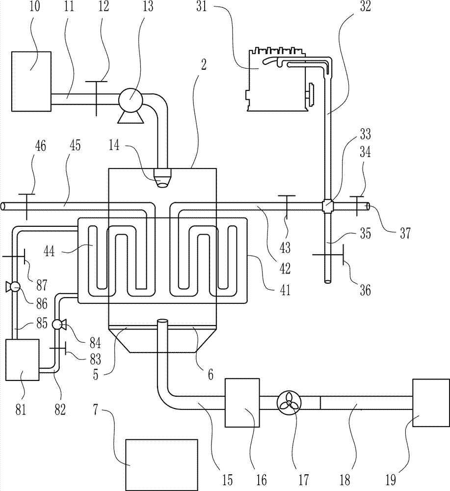
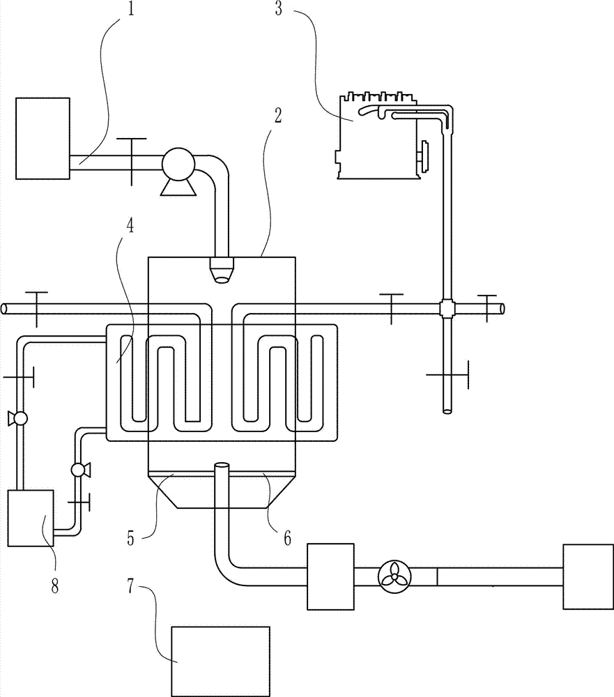
[0030] A waste heat reuse energy-saving spray drying tower, such as Figure 1-4 As shown, it includes a feeding spray device 1, a drying tower 2, a waste heat conveying device 3, an auxiliary preheating device 4, a left connecting rod 5, a right connecting rod 6, a receiving cylinder 7 and a water delivery device 8; the feeding spray device 1 and the drying The towers 2 are connected, and a waste heat conveying device 3 is installed on the upper right of the drying tower 2. A left connecting rod 5 and a right connecting rod 6 are arranged in the drying tower 2, and the left connecting rod 5 and the right connecting rod 6 are symmetrically arranged. , the left end of the left connecting rod 5 is fixedly connected with the inner wall of the drying tower 2, the right end of the right connecting rod 6 is fixedly connected with the inner wall of the drying tower 2, and the receiving cylinder 7 is arranged below the drying tower 2. The bottom of the tower 2 is provided with a port, ...
Embodiment 2
[0032] A waste heat reuse energy-saving spray drying tower, such as Figure 1-4 As shown, it includes a feeding spray device 1, a drying tower 2, a waste heat conveying device 3, an auxiliary preheating device 4, a left connecting rod 5, a right connecting rod 6, a receiving cylinder 7 and a water delivery device 8; the feeding spray device 1 and the drying The towers 2 are connected, and a waste heat conveying device 3 is installed on the upper right of the drying tower 2. A left connecting rod 5 and a right connecting rod 6 are arranged in the drying tower 2, and the left connecting rod 5 and the right connecting rod 6 are symmetrically arranged. , the left end of the left connecting rod 5 is fixedly connected with the inner wall of the drying tower 2, the right end of the right connecting rod 6 is fixedly connected with the inner wall of the drying tower 2, and the receiving cylinder 7 is arranged below the drying tower 2. The bottom of the tower 2 is provided with a port, ...
Embodiment 3
[0035] A waste heat reuse energy-saving spray drying tower, such as Figure 1-4 As shown, it includes a feeding spray device 1, a drying tower 2, a waste heat conveying device 3, an auxiliary preheating device 4, a left connecting rod 5, a right connecting rod 6, a receiving cylinder 7 and a water delivery device 8; the feeding spray device 1 and the drying The towers 2 are connected, and a waste heat conveying device 3 is installed on the upper right of the drying tower 2. A left connecting rod 5 and a right connecting rod 6 are arranged in the drying tower 2, and the left connecting rod 5 and the right connecting rod 6 are symmetrically arranged. , the left end of the left connecting rod 5 is fixedly connected with the inner wall of the drying tower 2, the right end of the right connecting rod 6 is fixedly connected with the inner wall of the drying tower 2, and the receiving cylinder 7 is arranged below the drying tower 2. The bottom of the tower 2 is provided with a port, ...
PUM
 Abstract
Description
Claims
Application Information
 - R&D Engineer
- R&D Manager
- IP Professional
- Industry Leading Data Capabilities
- Powerful AI technology
- Patent DNA Extraction
Browse by: Latest US Patents, China's latest patents, Technical Efficacy Thesaurus, Application Domain, Technology Topic.
© 2024 PatSnap. All rights reserved.Legal|Privacy policy|Modern Slavery Act Transparency Statement|Sitemap