Electronically-controlled electric brake caliper assembly

A technology of electric braking and electronic control, applied in the direction of braking actuators, etc., can solve the problems of long reaction time, low braking energy efficiency, complicated device structure, etc., achieve high energy utilization rate, simple structure, and reduce energy The effect of the delivery path

Active Publication Date: 2017-06-23
NINGBO GEELY AUTOMOBILE RES & DEV CO LTD
View PDF9 Cites 6 Cited by
  • Summary
  • Abstract
  • Description
  • Claims
  • Application Information

AI Technical Summary

Problems solved by technology

[0002] With the increasing popularity of automobiles, driving speed increases, energy saving and consumption reduction, driving safety is the top priority. Currently, hybrid, pure electric vehicles and ordinary diesel / gasoline vehicles mainly use two methods of braking devices-disc brakes and drum brakes. These two types of brakes are driven by hydraulic pressure or air pressure to press the friction pad against the rotor. Due to the compressibility of liquid / gas, the response lags and the response time is long (solenoid valve response time + hydraulic pressure / pneumatic pressure response time + Brake device reaction time), braking energy efficiency is low, of the two methods, devices such as a booster that amplifies the operating force applied to the brake pedal and a master cylinder that converts the operating force amplified by the booster into hydraulic pressure are required etc., which complicates the construction of the device

Method used


Image

  • Electronically-controlled electric brake caliper assembly
  • Electronically-controlled electric brake caliper assembly

Examples


Embodiment Construction

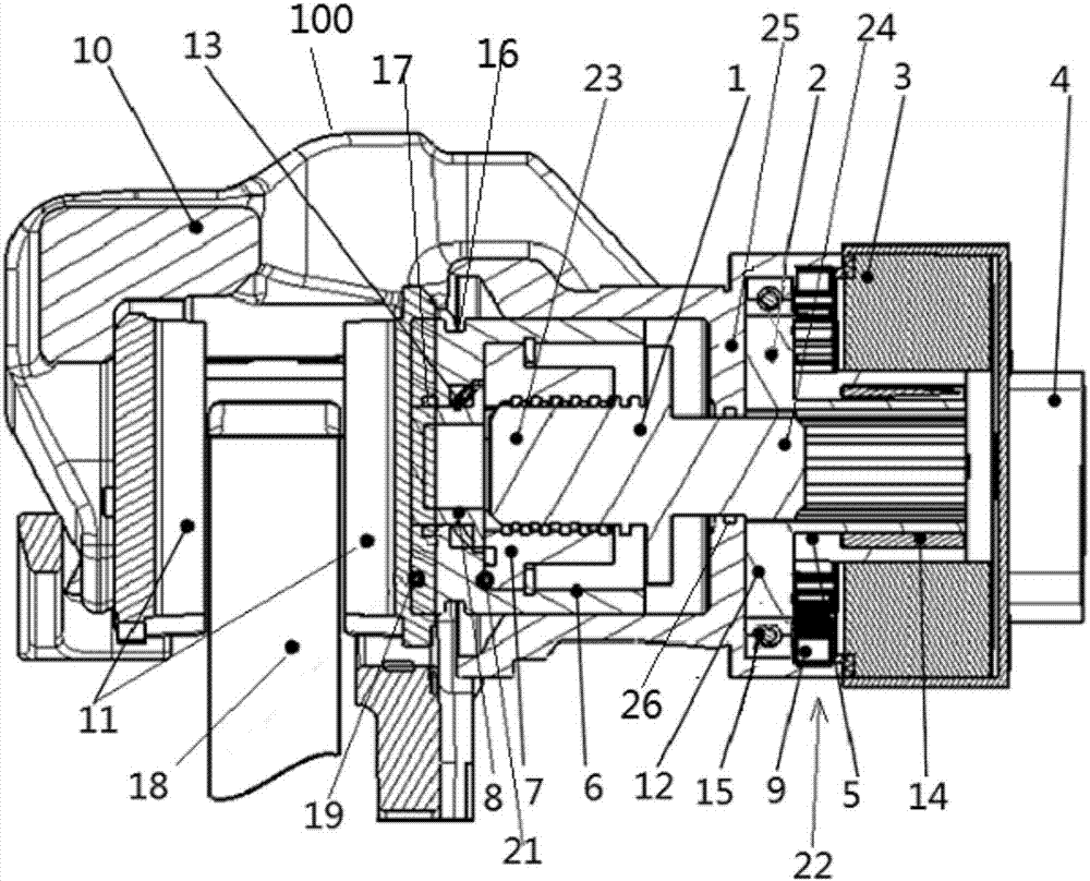
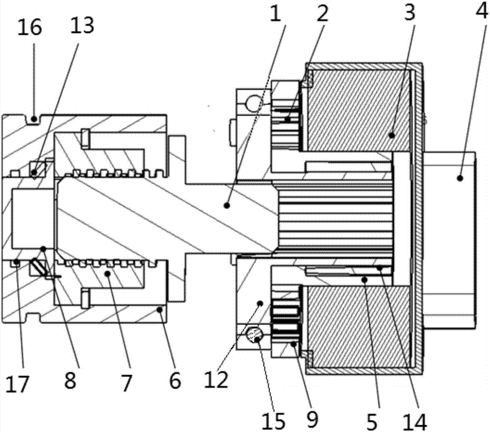
[0019] figure 1 It is a structural diagram of an electronically controlled electric brake caliper assembly according to an embodiment of the present invention. figure 2 It is a structure diagram of a motor planetary gear drive mechanism and a piston according to an embodiment of the present invention. combine figure 1 with figure 2 Do as follows. The electronically controlled electric brake caliper assembly includes a brake caliper 100 and a motor planetary gear drive mechanism 22 . Wherein the brake caliper 100 comprises a brake caliper body 10, a friction plate 11, a first piston 6, and a drive nut 7, wherein the friction plate 11, the first piston 6, and the drive nut 7 are assembled in the brake caliper body 10; The plates 11 are a pair and are arranged on both sides of the brake disc 18 for clamping the brake disc 18; the first end 19 of the first piston 6 abuts against one surface of the friction plate 11 to push the friction plate 11 Pressure; the second end 21 o...


PUM


Abstract

The invention provides an electronically-controlled electric brake caliper assembly and relates to the field of vehicle chassises. The electronically-controlled electric brake caliper assembly comprises a brake caliper body, a friction plate, a first piston, a driving nut, a planetary gear mechanism and a motor stator; the driving nut is fixedly mounted in the first piston; the first piston is fixedly arranged in the brake caliper body; and the motor stator drives the planetary gear mechanism and drives the first piston by a driving screw to push the friction plate to realize wheel brake. The electronically-controlled electric brake caliper assembly is capable of reducing energy transfer paths, high in response speed and also capable of performing emergency brake for a whole vehicle during power failure of the whole vehicle.

Description

technical field [0001] The invention relates to the field of vehicle chassis, in particular to an electronically controlled electric brake caliper assembly. Background technique [0002] With the increasing popularity of automobiles, driving speed increases, energy saving and consumption reduction, driving safety is the top priority. Currently, hybrid, pure electric vehicles and ordinary diesel / gasoline vehicles mainly use two methods of braking devices-disc brakes and drum brakes. These two types of brakes are driven by hydraulic pressure or air pressure to press the friction pad against the rotor. Due to the compressibility of liquid / gas, the response lags and the response time is long (solenoid valve response time + hydraulic pressure / pneumatic pressure response time + Brake device reaction time), braking energy efficiency is low, of the two methods, devices such as a booster that amplifies the operating force applied to the brake pedal and a master cylinder that converts...

Claims


Application Information

Patent Timeline
Patent Type & Authority Applications(China)
IPC IPC(8): F16D65/14
CPCF16D65/14
Inventor 周诗喜
Owner NINGBO GEELY AUTOMOBILE RES & DEV CO LTD
Why Eureka
Try Eureka