an air conditioning system

An air-conditioning system and evaporator technology, which is applied to the details of space heating and ventilation, household heating, heating methods, etc., can solve problems such as uneconomical operation, increased input force, and lower evaporating temperature, and avoid mixed pulsation and output. The effect of moderate air temperature and improved comfort

Active Publication Date: 2018-07-27
SHANGHAI HITACHI ELECTRICAL APPLIANCES CO LTD
View PDF7 Cites 0 Cited by
  • Summary
  • Abstract
  • Description
  • Claims
  • Application Information

AI Technical Summary

Problems solved by technology

Often in order to achieve the purpose of dehumidification, the evaporation temperature should be reduced as much as possible. For the compressor, the pressure ratio increases, the input force increases, and the operation is uneconomical.
At the same time, in order to achieve the lower evaporation temperature of the system for dehumidification, the temperature of the indoor air outlet is lower, and the comfort of the human body is poor.

Method used


Image

  • an air conditioning system
  • an air conditioning system

Examples


no. 1 example

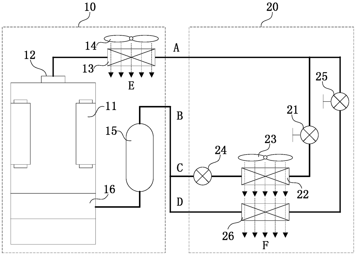
[0047] figure 1 It is a connection schematic diagram of the air conditioning system according to the first embodiment of the present invention. Such as figure 1 As shown, an air conditioning system of the present invention includes: an outdoor unit 10 and an indoor unit 20 . Wherein, the outdoor unit 10 includes a compressor 11 , a condenser 13 , a first fan 14 and a liquid accumulator 15 . The first end of the condenser 13 is connected to the exhaust port 12 of the compressor 11 , and the second end is connected to the air inlet A of the indoor unit 20 . A first end of the accumulator 15 is connected to the liquid outlet B of the indoor unit 20 , and a second end is connected to the compression chamber 16 of the compressor 11 . The air duct E of the first fan 14 passes through the condenser 13 .

[0048] The indoor unit 20 includes a first pipeline and a second pipeline connected in parallel. The first pipeline includes a first electronic expansion valve 21, a first evapo...

specific Embodiment approach

[0052] The indoor evaporator of the present invention is divided into two parts: the first evaporator 22 is a high-temperature evaporator (mainly responsible for sensible heat load), and the second evaporator 26 is a low-temperature evaporator (mainly responsible for latent heat load). After the exhaust gas from the compressor enters the condenser 13, it is divided into two paths, each of which enters two evaporators with different evaporation temperatures, and the refrigerant flow rate entering the evaporator and the air volume of the indoor unit are adjusted through their respective electronic expansion valves to realize the first evaporator 22 and the second evaporator 26 work at two different evaporating temperatures; at the same time, a back pressure valve is set at the outlet of the evaporator (the first evaporator 22) with a higher evaporating temperature. The pressure of the refrigerant at the outlet of the low evaporator (second evaporator 26) is close; after the two r...

no. 2 example

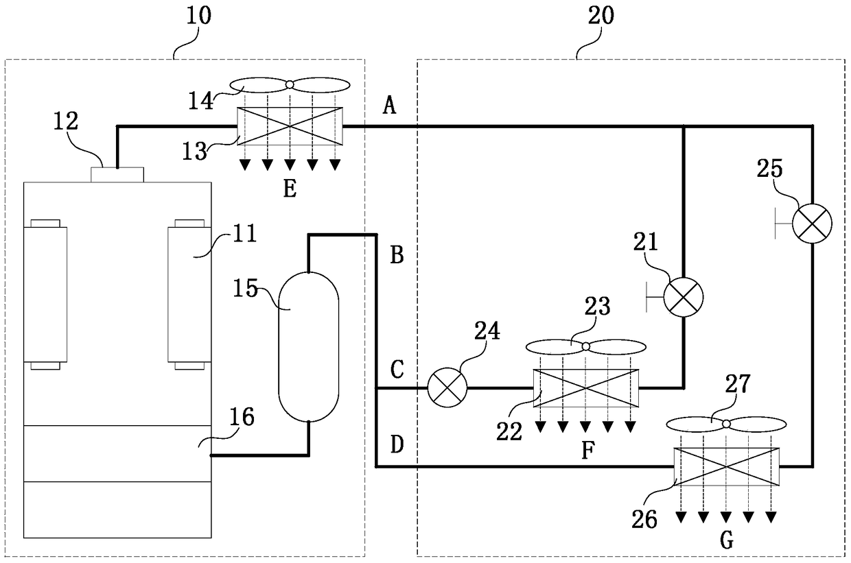
[0056] figure 2 It is a connection schematic diagram of the air conditioning system according to the second embodiment of the present invention. Such as figure 2 As shown, another air conditioning system of the present invention is the same as the first embodiment in that the air conditioning system includes: an outdoor unit 10 and an indoor unit 20 . Wherein, the outdoor unit 10 includes a compressor 11 , a condenser 13 , a first fan 14 and a liquid accumulator 15 . The first end of the condenser 13 is connected to the exhaust port 12 of the compressor 11 , and the second end is connected to the air inlet A of the indoor unit 20 . The first end of the accumulator is connected to the liquid outlet B of the indoor unit 20 , and the second end is connected to the compression chamber 16 of the compressor 11 . The air duct E of the first fan 14 passes through the condenser 13 .

[0057] The indoor unit 20 includes a first pipeline and a second pipeline connected in parallel....


PUM


Abstract

The invention provides an air conditioning system. The air conditioning system includes an outdoor unit and an indoor unit. The outdoor unit comprises a compressor, a condenser, and a reservoir. A first end of the condenser is connected with an air outlet of the compressor, a second end is connected with an air inlet of the indoor unit; a first end of the reservoir is connected with a liquid outlet of the indoor unit, a second end is connected with a compression chamber of the compressor; the indoor unit comprises a first pipeline and a second pipeline, the first pipeline and the second pipeline are connected in parallel; the first pipeline comprises a first electronic expansion valve, a first evaporator and a back pressure valve, and the first electronic expansion valve, the first evaporator and the back pressure valve are connected in parallel; the second pipeline comprises a second electronic expansion valve and a second evaporator, the first electronic expansion valve and the second evaporator are connected in parallel, and the evaporating temperature of the first evaporator is higher than that of the second evaporator. The air conditioning system can guarantee that evaporating pressure in outlets of two evaporators with different evaporating pressure are the same, prevent the suction side of the compressor from pulsating mixed, and accordingly the suction side of the compressor maintains steady, and the reliability is guaranteed.

Description

technical field [0001] The invention relates to an air conditioning system, in particular to an air conditioning system with two evaporation temperatures. Background technique [0002] At present, the method of humid air condensation dehumidification is used to remove indoor residual humidity. The surface temperature of the evaporator needs to be lower than the dew point temperature of the indoor air. Considering the temperature difference between heat transfer and medium delivery, for example, to achieve a dew point temperature of 16.6°C requires an evaporation temperature below 7°C. . Often in order to achieve the purpose of dehumidification, the evaporation temperature should be reduced as much as possible. For the compressor, the pressure ratio increases, the input force increases, and the operation is uneconomical. At the same time, in order to achieve the lower evaporation temperature for the purpose of dehumidification, the system makes the indoor air outlet temperat...

Claims


Application Information

Patent Timeline
Patent Type & Authority Patents(China)
IPC IPC(8): F25B5/02F24F13/30
CPCF24F13/30F25B5/02F25B2600/0272
Inventor 张蕾张海锋傅海莹
Owner SHANGHAI HITACHI ELECTRICAL APPLIANCES CO LTD
Why Eureka
Try Eureka