
Rectangular forming antenna array

An antenna array and shaping technology, which is applied to antennas, antenna unit combinations with different polarization directions, electrical components, etc., can solve the problems of high side lobes and insufficient fall of the outer lobes at the half-power angle, and achieve low side lobes. , Good rectangular beamforming effect, cost saving effect

Active Publication Date: 2017-06-23
BEIJING INST OF SPACECRAFT SYST ENG
View PDF3 Cites 15 Cited by
  • Summary
  • Abstract
  • Description
  • Claims
  • Application Information

AI Technical Summary

Problems solved by technology

[0009] In order to solve the problems existing in the prior art and overcome the difficulties of the prior art, the present invention proposes a design scheme of a rectangular shaped antenna array with a rapid drop in the pattern, which solves the problem of the outer lobe drop of the half power angle of the rectangular shaped antenna For the problem of not fast enough and high sidelobe, through array layout, amplitude weighting, and phase configuration, a rectangular shaped beam with a rapid drop in the pattern is realized, and the array antenna uses fewer units, which can effectively meet the requirements of miniaturization and low weight

Method used


Image

  • Rectangular forming antenna array
  • Rectangular forming antenna array
  • Rectangular forming antenna array

Examples


Embodiment Construction

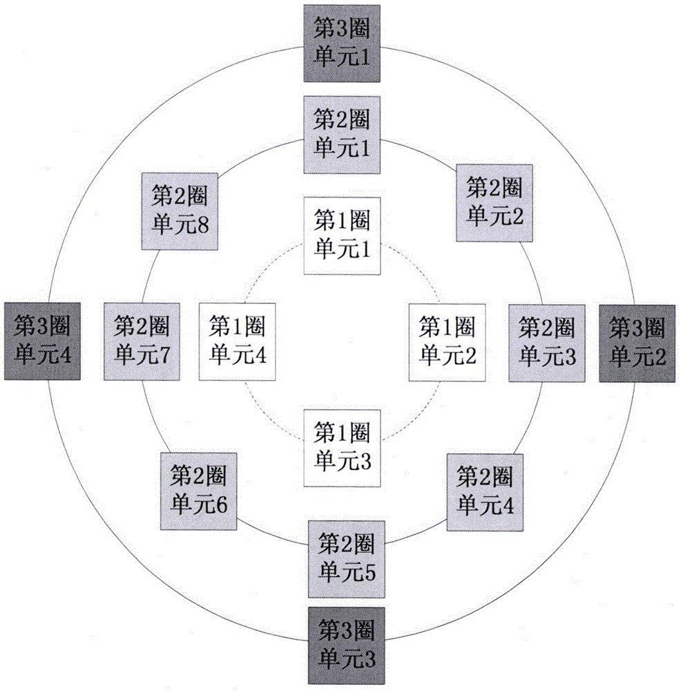
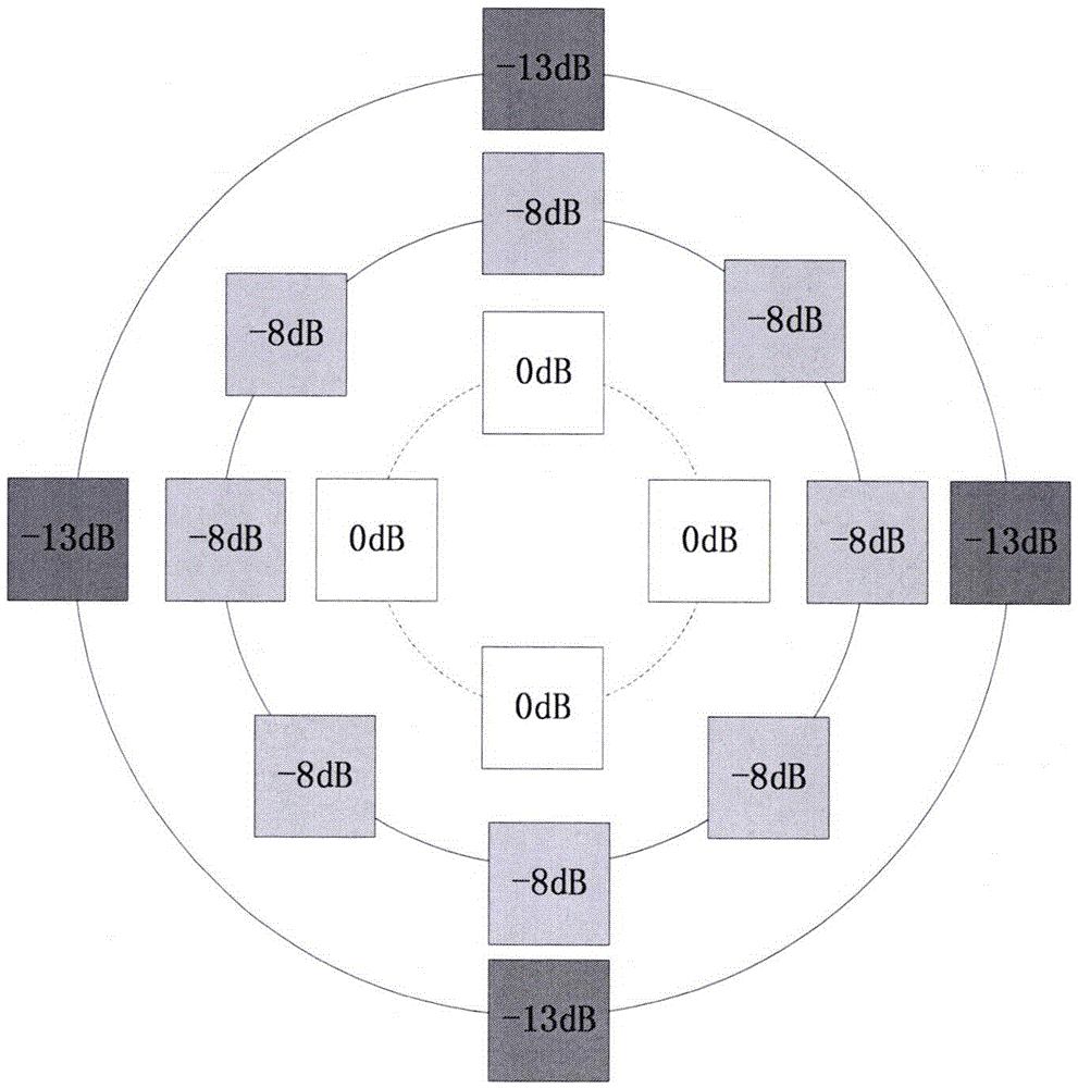
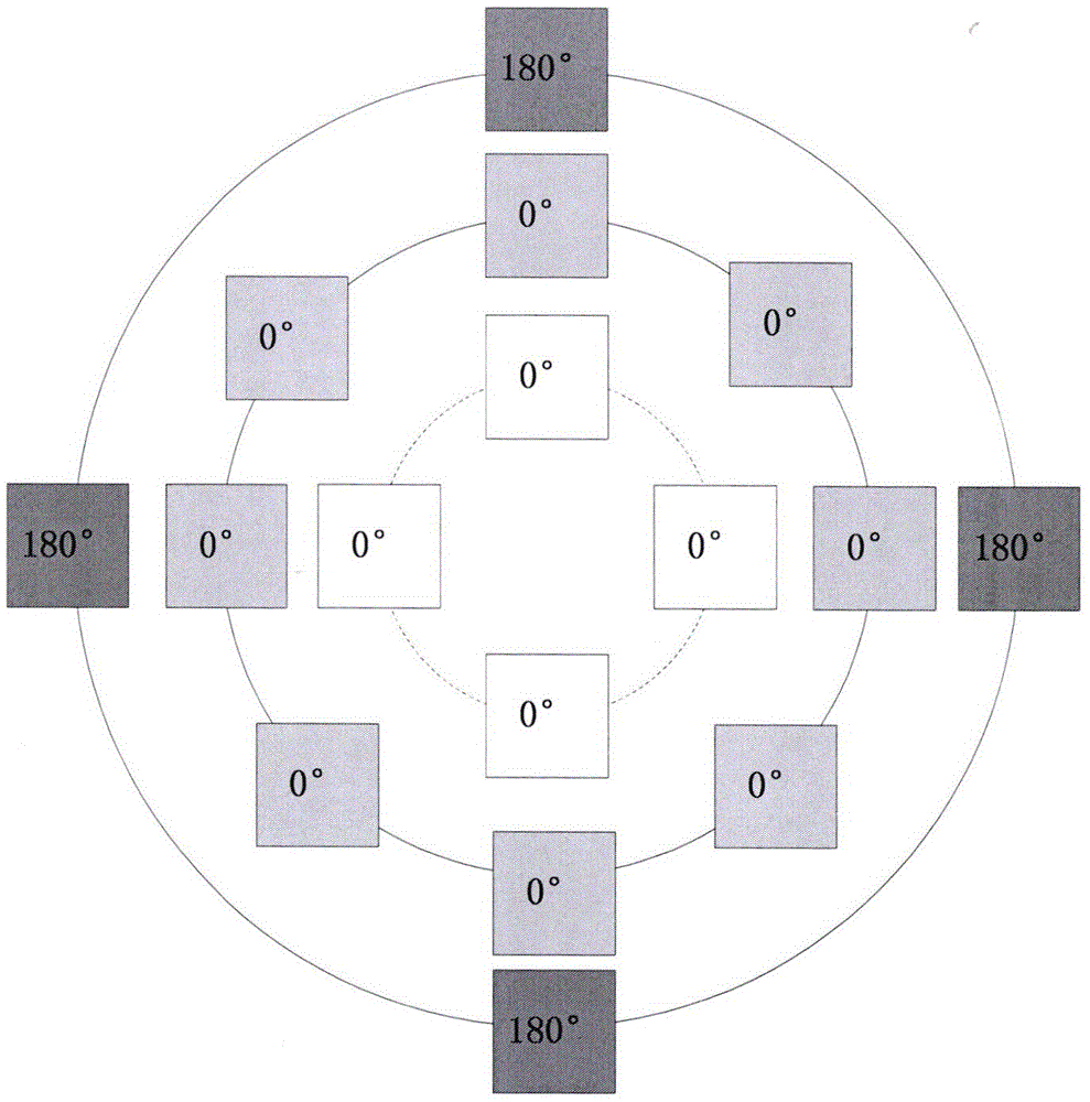
[0026] It should be understood that the present invention includes the layout, amplitude weighting and phase configuration of the shaped antenna array unit. The array unit is the same cross dipole antenna, patch antenna or waveguide antenna, and the array layout is 4 array units in the first circle , 8 array units in the second circle, and 4 array units in the third circle. The feeding amplitude of the array units in the first circle is the largest, and the feeding amplitude of the array units decreases successively from the inner circle to the outer circle, and the feeding amplitudes of the array units in each circle are consistent. The array feed phase is the same as the feed phase of the 4 array units in the first circle and the 8 array units in the second circle, and the feed phase of the 4 array units in the third circle is the same as the feed phase of other array units The difference is 180°.

[0027] Attached below Figure 1-5 and specific embodiments to describe the...


PUM


Abstract

The invention provides a rectangular forming antenna array. Rectangular forming beams, capable of rapid falling, of a directional diagram can be realized through array layout, amplitude weighting, and phase configuration by employing a few of array units of forming antennas. The rectangular forming antenna array comprises four array units of a first loop, eight array units of a second loop, and four array units of a third loop, and the array units of the three loops are concentric. Therefore, by employing the rectangular forming antenna array, coverage overlapping or dead zones of adjacent multiplexing cells can be effectively eliminated, a better effect of rectangular beam forming is realized, the minor lobe is reduced, the quantity of array units is reduced, miniaturized and low-weight design of the rectangular forming antennas is realized, the rectangular forming antenna array can be better applied to the field of mobile communication etc., and goals of reducing the cost and saving the time can be achieved.

Description

technical field [0001] The invention belongs to the technical field of antennas and wireless communications, and relates to a rectangular shaped antenna array with rapidly falling pattern, which realizes the rectangular shaped beam with fast falling pattern through array layout, amplitude weighting and phase configuration. Background technique [0002] A shaped antenna refers to an antenna that can generate a specific beam shape. The purpose is to increase the strength of the wireless signal in a specific area while reducing the interference in other areas. Usually, the array antenna technology is used to optimize the design of the antenna surface field distribution to obtain the desired Far-field beam shape. [0003] In mobile communication technology, a large service area is usually divided into multiple cells to provide mobile communication services respectively, and each cell needs to be equipped with an antenna for transmitting and receiving wireless signals. However, ...

Claims


Application Information

Patent Timeline
IPC IPC(8): H01Q21/24H01Q3/30
Inventor 张涛江涛韩运忠李鸿斌高文军
Owner BEIJING INST OF SPACECRAFT SYST ENG
Learn More