PWM rectifier with consideration of power quality control and controlling method thereof

A power quality and control method technology, applied in electrical components, circuit devices, AC network circuits, etc., can solve the problems of theoretical parameter and actual parameter errors, aperiodic interference signals are difficult to eradicate, difficult to eradicate, etc., to reduce fluctuations Influence and reduce the effect of mutual interference

Active Publication Date: 2017-06-23
蔡蔚
View PDF3 Cites 2 Cited by
  • Summary
  • Abstract
  • Description
  • Claims
  • Application Information

AI Technical Summary

Problems solved by technology

However, since the repetitive control method mentioned in this method uses the reactive power and harmonics calculated in the previous period as the compensation command signal, its detection delay is relatively large and inherently difficult to eradicate, and it is difficult for non-periodic interference signals It is even more difficult to deal with abrupt active, reactive and harmonic signals
Secondly, the method mentioned in this method obtains the control law of the interconnection and damping configuration based on the port-controlled dissipation Hamilton model of the PWM rectifier through the Lagrangian-Charpy integral method. However, the calculation of this method is complicated. There is always a certain error between the theoretical parameters and actual parameters of the equipment, so too fine a control method will make it difficult for engineers to set reasonable control parameters
Finally, the invention does not optimize the remaining capacity for voltage-type PWM control, nor does it involve coordinated control among multiple rectifier modules

Method used


Image

  • PWM rectifier with consideration of power quality control and controlling method thereof
  • PWM rectifier with consideration of power quality control and controlling method thereof
  • PWM rectifier with consideration of power quality control and controlling method thereof

Examples


Embodiment 1

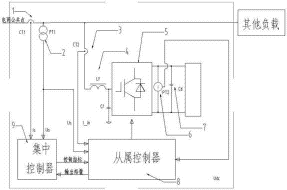
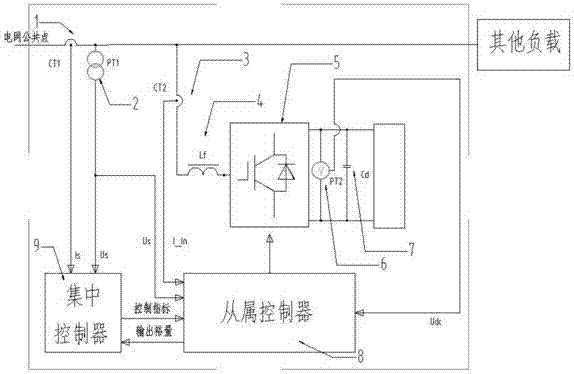
[0026] See figure 1 and figure 2 , the PWM rectifier of this embodiment has a set of rectifier main circuit and slave controller, specifically including: grid voltage sensor 1, grid current sensor 2, input current sensor 3, input filter 4, rectifier main circuit 5, output voltage sensor 6 , an output filter capacitor 7, a slave controller 8, and a centralized controller 9. in, figure 1 The input filter 4 shown is of the LC type, figure 2 The shown input filter 4 is L-shaped; the rectifier main circuit 5 adopts an H-bridge or any other type of rectifier with four-quadrant working capability. In order to be connected to a power grid with a higher voltage level, an AC transformer (not shown) may be installed at the front end of the PWM rectifier in this embodiment.

[0027] specifically,

[0028]The grid voltage sensor 1 and the grid current sensor 2 are coupled between the grid common point and the centralized controller 9, and the grid voltage sensor 1 and the grid curre...

Embodiment 2

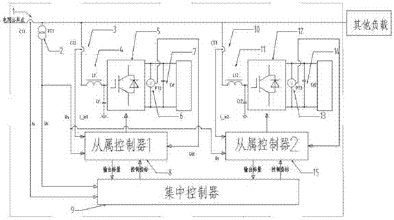
[0033] See image 3 and Figure 4 , the PWM rectifier of this embodiment has two sets of rectifier main circuits and slave controllers, specifically including: grid voltage sensor 1, grid current sensor 2, first input current sensor 3, first input filter 4, first rectifier main circuit 5. The first output voltage sensor 6, the first output filter capacitor 7, the first slave controller 8, the centralized controller 9, the second input current sensor 10, the second input filter 11, the second rectifier main circuit 12, the second Two output voltage sensors 13 , a second output filter capacitor 14 , and a second slave controller 15 . in, image 3 The first input filter 4 and the second input filter 11 shown are of LC type, Figure 4 The first input filter 4 and the second input filter 11 shown can also be L-type; the first rectifier main circuit 5 and the second rectifier main circuit 12 can also be H bridges or any other type with four-quadrant operation capability of the r...

Embodiment 3

[0037] This embodiment discloses a control method for a PWM rectifier. The PWM rectifier of the present invention has the following operating modes: outputting active power, or feeding back active power, or injecting reactive power and / or harmonics to the grid common point when outputting active power When suppressing or feeding back active power, reactive power and / or harmonic suppression are injected into the grid common point. The present invention is not limited to the application of the three-phase circuit, and the method of the present invention can also be implemented in a single-phase system by constructing a three-phase circuit signal and the like.

[0038] The control method of the PWM rectifier comprises the following steps:

[0039] 1) The slave controller judges whether the grid needs active power feedback. If not, the PWM rectifier enters the energy absorption mode to absorb the grid active power and provide energy to the DC side. At the same time, the slave cont...


PUM


Abstract

The invention discloses a PWM rectifier with consideration of power quality control. The PWM rectifier comprises a central controller, at least one slave controller, and at least one rectifier main circuit. In addition, the controlling method includes: the slave controller introduces power feedward decoupling into a power inner-loop controller based on a grid need to control the rectifier main circuit to carry out reactive compensation and / or harmonic suppression. The PWM rectifier and the controlling method have the following advantages: an energy absorption mode and an energy feedback mode are realized and reactive compensation and / or harmonic suppression can be carried out in the two kinds of modes, so that a primary objective of completing active power transmission of a direct-current side can be achieved; and a power quality problem with common point existence can be solved by fully using the residual capacity of the PWM rectifier and energy storage capacity of the energy storage type load.

Description

technical field [0001] Embodiments of the present invention relate to a rectifier and a control method thereof, in particular, to a PWM rectifier and a control method thereof taking into account power quality control. Background technique [0002] With the continuous advancement of power electronics technology, voltage-type PWM rectifiers are being used more widely. [0003] The voltage-type PWM rectifier uses voltage loop control to realize output voltage control, so that the DC voltage obtained by the load can track a given reference voltage value. Most grid-connected PWM rectifiers are voltage-type PWM rectifiers, which are characterized by controlling the DC side voltage to stabilize. At present, the rectifiers actually used in static var generators (SVG), active power (APF), and dynamic voltage restorers (DVR) are voltage-type PWM rectifiers, because these power quality control devices need to keep the DC side voltage stable, So active power must be absorbed from the ...

Claims


Application Information

Patent Timeline
Patent Type & Authority Applications(China)
IPC IPC(8): H02J3/01H02J3/18H02M7/72
CPCH02J3/01H02J3/1821H02M7/72Y02E40/30Y02E40/40
Inventor 蔡蔚
Owner 蔡蔚
Why Eureka
Try Eureka