
CAN message loss monitoring method

A technology of message loss and message, applied in digital transmission systems, electrical components, transmission systems, etc., can solve problems such as message M1 loss failure, message M2 loss failure, etc., to solve DTC false alarms and DTC missed alarms , Improve maintainability, practical effect is remarkable

Active Publication Date: 2017-06-23
CHINA FIRST AUTOMOBILE
View PDF9 Cites 6 Cited by
  • Summary
  • Abstract
  • Description
  • Claims
  • Application Information

AI Technical Summary

Problems solved by technology

Some manufacturers start to monitor the loss of CAN messages in the ACC file. At this time, ECU2 cannot send the message M2 because it is not powered on, which causes ECU3 to falsely report the message M2 loss failure; some manufacturers delay the monitoring until the ON file If the CAN message is lost, when the ignition switch is in the ACC gear, ECU3 receives the periodic message M1 and does not monitor whether the message is lost, which will easily lead to ECU3 missing the message M1 loss failure

Method used


Image

  • CAN message loss monitoring method
  • CAN message loss monitoring method
  • CAN message loss monitoring method

Examples


Embodiment Construction

[0054] In order to make the technical problems, technical solutions and advantages to be solved by the present invention clearer, a detailed description will be given below in conjunction with the drawings and specific embodiments.

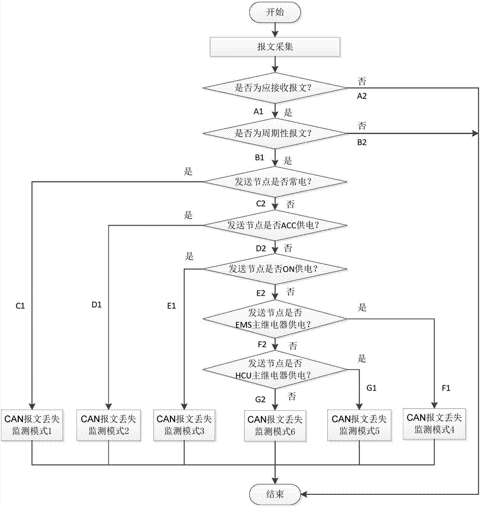
[0055] The CAN message loss monitoring method provided by the present invention is used for monitoring the loss of CAN messages sent by nodes on all network segments in the CAN network. There are multiple nodes on each network segment. Each node can send multiple CAN messages to other nodes, and can also receive CAN messages from other nodes. When receiving messages from other nodes, you can set the The counter on the node monitors the loss of the received CAN message.

[0056] figure 1 It is a schematic flow diagram of monitoring the loss of a CAN message received by a certain node in a certain network segment in the CAN network of the present invention. The CAN message reception status of all other nodes in the CAN network can be figure 1 The monito...


PUM


Abstract

The invention discloses a CAN (Controller Area Network) message loss monitoring method comprising the following steps: S100, a network receiving node collects a CAN message from a network sending node; S200, the network receiving node judges whether the collected message is a message which should be received by the network node, the method goes to S300 if the collected message is a message which should be received by the network node, and message processing ends if the collected message is not a message which should be received by the network node; S300, the network receiving node judges whether the message is a periodic message, the method goes to S400 if the message is a periodic message, and message processing ends if the message is not a periodic message; and S400, the network receiving node judges the power supply mode of a sending node of a message to be collected, and adopts different CAN message loss monitoring modes based on different power supply modes of sending nodes. According to the invention, as different CAN message loss monitoring modes are adopted for ECUs (Electronic Control Unit) adopting different power supply modes in a CAN network, the problem of failure caused by false or missing report of CAN message loss is avoided.

Description

Technical field [0001] The invention belongs to the technical field of automotive controller area network (Controller Area Network, CAN for short) network communication, and specifically relates to a method for monitoring loss of CAN messages. Background technique [0002] If node 1 receives one or more messages from node 2, node 2 is called node 1's partner node. In order to improve the maintainability of the vehicle CAN network, all electronic control units (ECUs for short) in the network should include a message loss monitoring mechanism for periodic messages sent by all partner nodes, and store corresponding monitoring results according to the monitoring results. CAN message lost fault code. [0003] Patent Document 1 (Publication Number: CN102404170A; Publication Date: April 4, 2012) discloses a method, device, and system for detecting packet loss. The patent receives too many packets per unit time and sends and receives packets. The overall situation of network communicatio...

Claims


Application Information

Patent Timeline
IPC IPC(8): H04L12/24H04L12/26H04L12/823H04L47/32
CPCH04L41/0604H04L43/0823H04L47/32
Inventor 张丽波马东扬何俊婷玄国勋
Owner CHINA FIRST AUTOMOBILE
Learn More