A Local Springback Compensation Method of Die Surface Based on Ellipse Surface Mapping Drive

A technology of mold profile and springback compensation, applied in special data processing applications, instruments, electrical digital data processing, etc., can solve the problems of partial size of parts not meeting tolerance requirements, poor surface quality, and inability to use molds to manufacture, etc. Improve the efficiency of local springback compensation, reduce the amount of training, and shorten the mold manufacturing cycle

Active Publication Date: 2018-08-24
CHINA FIRST AUTOMOBILE
View PDF7 Cites 0 Cited by
  • Summary
  • Abstract
  • Description
  • Claims
  • Application Information

AI Technical Summary

Problems solved by technology

Springback compensation is currently recognized by the mold industry as the main means of solving product size deviations. The main advantage of the CAE analysis software currently used in production is the overall springback compensation of the mold surface, but the quality of the surface directly output after compensation is poor, such as figure 1 As shown in Fig. 1, after compensation, there are alternating convex and concave wavy areas on the surface, which cannot be used for mold manufacturing, and special smoothing treatment is required.
In the mold debugging stage, due to the influence of various factors such as the calculation accuracy of CAE software, the mold surface after springback compensation will still cause the local dimensions of the part to fail to meet the tolerance requirements, and it is unavoidable that the mold surface needs to be rectified

Method used


Image

  • A Local Springback Compensation Method of Die Surface Based on Ellipse Surface Mapping Drive
  • A Local Springback Compensation Method of Die Surface Based on Ellipse Surface Mapping Drive
  • A Local Springback Compensation Method of Die Surface Based on Ellipse Surface Mapping Drive

Examples


Embodiment 1

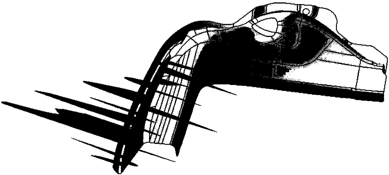
[0049] The product model of the side wall and rear reinforcement plate of a certain car model is as follows: Figure 4 As shown, the product is a left-right symmetrical piece, and the stamping process is designed as one mold and two pieces. In order to evaluate the dimensional accuracy of the product, the simulation is carried out in the AutoForm simulation software according to the content of the stamping process. Figure 5 Shown is the springback distribution cloud map of the product. The springback result shows that the local springback value of the product exceeds the tolerance range. The tolerance requirement is ±0.5mm. Springback compensation is required. The steps are as follows:

[0050] The first step is to obtain the cloud map of the local springback distribution of the part, and the sub-steps are:

[0051] ① Export the springback parts from AutoForm software in stl file format;

[0052] ② Import the stl file into the Digitized Shape Editor module of CATIA software,...

Embodiment 2

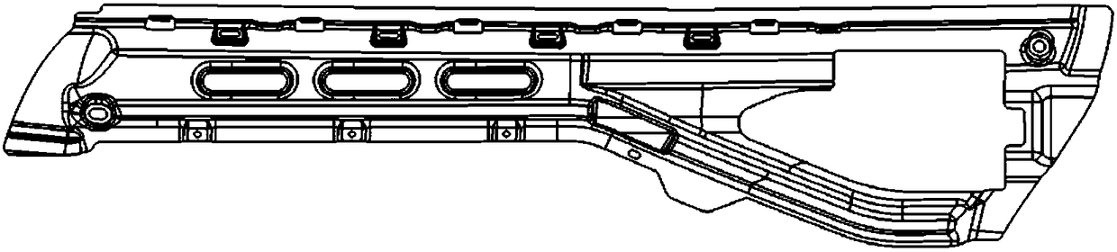
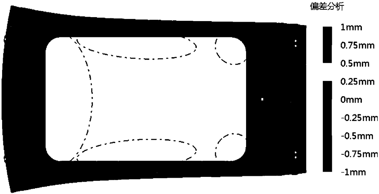
[0072] Figure 14 Shown is the product model of the door reinforcement plate of a certain car model. The product is a left-right symmetrical part. The stamping process is designed as one mold and two pieces. The stamping of the product is completed by using a 3-sequence mold. After the mold is qualified, the first round of stamping test is carried out. Figure 15 As shown, the optical inspection found that the local size of the trial punched part exceeded the tolerance range, and it is necessary to perform springback compensation on the surface of the current drawing convex model. The following takes the negative springback area at the end of the part as an example to perform local springback compensation. The steps are as follows :

[0073] The first step is to obtain the cloud map of the local springback distribution of the part, and the sub-steps are:

[0074] ① Export the point cloud data obtained by optical inspection in stl file format;

[0075] ②Import the stl file in...


PUM


Abstract

The invention relates to a die profile local springback compensation method based on elliptical surface mapping drive. The die profile local springback compensation method based on the elliptical surface mapping drive comprises the following steps that firstly, a local springback distribution cloud map of a part is obtained; secondly, a drive coordinate system is established according to the cloud map, an elliptical sketch is drawn, an interior area of the elliptical sketch is defined as a springback compensation area, and a reference curved surface and a target curved surface are established according to the springback compensation area and the springback compensation amount; and finally, the die profile is driven to deform in a mapping manner with the reference curved surface and the target curved surface as the deformation criterion and with the Z-axis direction of the drive coordinate system as a deformation direction, and the local springback compensation of the product is completed. Compared with the prior art, the die profile local springback compensation method based on the elliptical surface mapping drive has the beneficial effects that the efficiency of local springback compensation of the profile of a stamping die is improved, the local springback compensation precision of the profile of the die and the curved surface quality of the compensated profile of the die are effectively guaranteed, the die research and study amount is reduced, and the manufacturing cycle of the die is shortened.

Description

Technical field: [0001] The invention relates to a local springback compensation method of a mold surface based on an ellipse surface mapping drive, and belongs to the technical field of stamping mold manufacturing for automobile panels. Background technique: [0002] With the increasing speed of automobile replacement and the continuous improvement of the quality requirements for the appearance of the car body, the stamping die, as an important car body manufacturing equipment, puts forward higher requirements for its manufacturing cycle and quality. The main factor of manufacturing cycle and stamping quality. Springback compensation is currently recognized by the mold industry as the main means of solving product size deviations. The main advantage of the CAE analysis software currently used in production is the overall springback compensation of the mold surface, but the quality of the surface directly output after compensation is poor, such as figure 1 As shown in Fig. ...

Claims


Application Information

Patent Timeline
Patent Type & Authority Patents(China)
IPC IPC(8): G06F17/50B21D3/16
CPCB21D3/16G06F30/17
Inventor 王刚张健闫巍
Owner CHINA FIRST AUTOMOBILE
Why Eureka
Try Eureka