
High-precision numerical control turning lathe

A technology of CNC lathes and ordinary lathes, applied in the directions of large fixed members, maintenance and safety accessories, feeding devices, etc., to achieve the effect of saving manpower and low cost

Inactive Publication Date: 2017-06-27
TIANJIN TAIJIN TECH DEV CO LTD
View PDF0 Cites 0 Cited by
  • Summary
  • Abstract
  • Description
  • Claims
  • Application Information

AI Technical Summary

Problems solved by technology

[0003] The purpose of the present invention is to solve the problems existing in the existing manual lathe, by adding a computer control box and controlling the motor, so that the ordinary lathe becomes an automatic, precise, efficient and flexible CNC lathe

Method used


Image

  • High-precision numerical control turning lathe

Examples


Embodiment Construction

[0011] The present invention will be described in further detail below in conjunction with the accompanying drawings and specific embodiments. It should be understood that the specific embodiments described here are only used to explain the present invention, and are not used to limit the protection scope of the present invention.

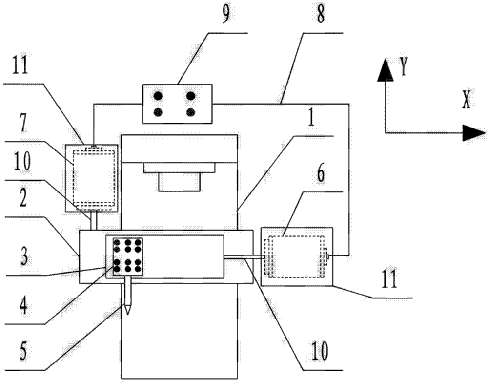
[0012] see figure 1 , a high-precision numerically controlled lathe, comprising a common lathe body 1, a large supporting plate 2 capable of moving back and forth along the top of the common lathe body 1, a middle supporting plate 3 capable of moving left and right above the large supporting plate 2, and a middle supporting plate 3 A tool holder 4 is arranged above, and a cutter 5 is fixedly arranged on the tool holder 4 . The large supporting plate 2 is connected with the Y-axis motor 7 through the leading screw 10, and the connection between the large supporting plate 2 and the leading screw 10 enables the Y-axis motor 7 to drive the large suppo...


PUM


Abstract

The invention relates to a high-precision numerically controlled lathe, which comprises a common lathe body, a large pallet, a middle pallet and a tool holder. A large supporting plate capable of moving back and forth along its Y axis is installed above the ordinary lathe body, a middle supporting plate capable of moving back and forth along the X axis is arranged above the large supporting plate, and a tool holder is arranged above the middle supporting plate. A cutter is installed on the tool holder, the large supporting plate is connected with the Y-axis motor through a leading screw, and the middle supporting plate is connected with the X-axis motor through a leading screw. The invention has the advantages of being automatic, precise, efficient, flexible, and low in cost, and is suitable for small and medium-sized machining enterprises to improve existing common lathes.

Description

technical field [0001] The invention relates to the field of mechanical processing equipment, in particular to a high-precision numerical control lathe. Background technique [0002] In lathe processing, manual cranking is often used to control the movement of the large pallet and the middle pallet. When the manual lathe is processing the workpiece, the accuracy of the action is not accurate enough due to some factors, which will affect the accuracy and surface quality of the workpiece. Contents of the invention [0003] The purpose of the present invention is to solve the problems existing in the existing manual lathes, by increasing the computer control box and controlling the motors, the ordinary lathes can be turned into automatic, precise, efficient and flexible numerically controlled lathes. [0004] The present invention is realized through the following technical solutions: [0005] A high-precision numerically controlled lathe, including a general lathe body, a l...

Claims


Application Information

Patent Timeline
Patent Type & Authority Applications(China)
IPC IPC(8): B23B21/00B23Q1/00B23Q11/08B23Q5/28
CPCB23Q1/26B23Q1/0009B23Q5/28B23Q11/08B23Q2701/01B23Q2705/102B23Q2705/182
Inventor 戴俊生
Owner TIANJIN TAIJIN TECH DEV CO LTD
Learn More