
Multi-stage series mobile power supply system

A technology of mobile power supply and power supply system, applied in the direction of collectors, electric vehicles, electric traction, etc., can solve the problems of short working time, small battery capacity, inconvenient to remove and plug, achieve simple structure and operation, avoid rectification And the effect of frequency conversion and long continuous working time

Active Publication Date: 2017-06-27
杭州蓝力电动科技有限公司
View PDF5 Cites 1 Cited by
  • Summary
  • Abstract
  • Description
  • Claims
  • Application Information

AI Technical Summary

Problems solved by technology

[0002] For example, when electric construction machinery such as excavators are powered by mobile power supply vehicles, considering the mobility of the excavator, as well as the transportability and hoisting of the power supply vehicles, it is hoped that the power supply vehicles can be as small as possible, light in weight, and reliable. This will inevitably cause the battery capacity to be small, and the working time can be maintained for a short time. In addition, during the working process of the excavator, it is inconvenient to remove and plug the plug of the power transmission line in order to replace the power supply vehicle. time doesn't work
[0003] One solution is to use multiple power supply vehicles with the same main circuit structure to connect them in series to supply power. Each power supply vehicle is only different in battery capacity and some auxiliary functions, so that the power output of the latter power supply vehicle can be plugged into the previous power supply. On the charging interface of the vehicle, let the latter power supply vehicle supply power to the front electric construction machinery through the previous power supply vehicle, but because the power supply vehicle uses the AC power converted from direct current through the inverter to output externally, such a current The frequency components are very complex, so it is not suitable as a charging power source for the next power supply vehicle, and multi-stage rectification and frequency conversion will also bring more power loss

Method used


Image

  • Multi-stage series mobile power supply system
  • Multi-stage series mobile power supply system
  • Multi-stage series mobile power supply system

Examples


specific Embodiment 1

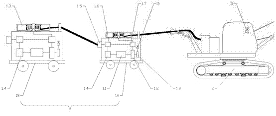
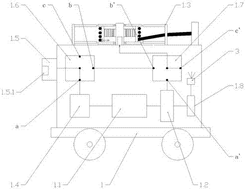
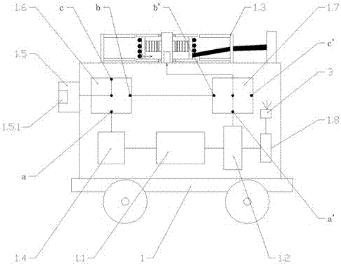
[0027] Specific embodiment one: as figure 1 As shown, the multi-stage series mobile power supply system includes at least one mobile power supply vehicle 1 and electric construction machinery 2 (here is an electric excavator), the mobile power supply vehicle 1 provides electric power for the electric construction machinery 2, and the mobile power supply vehicle 1 One or more units are connected in series to the electric construction machinery 2, and the series connection is that the cable of 1.3 in the cable retracting device of the rear mobile power supply vehicle 1 is connected to the receiving power of the previous mobile power supply vehicle 1. on device 1.5. The mobile power supply vehicle 1 is equipped with a storage battery 1.1, an output power conversion device 1.2, a cable retracting device 1.3, a charging device 1.4, a power receiving device 1.5, an input power conversion switch 1.6 and an output power conversion switch 1.7, and the cable retracting device 1.3 is equ...

specific Embodiment 2

[0038] Specific embodiment two: in combination with embodiment one, each mobile power supply vehicle 1 can have retractable cables ranging from tens of meters to hundreds of meters, by two or more mobile power supply vehicles 1 connected to each other, And on the power receiving device 1.5 of the last mobile power supply vehicle 1, it is connected to the grid power supply, and the manager of the electric construction machinery 2 or the mobile power supply vehicle 1 can communicate with each mobile power supply vehicle 1 through the communication device 3. The control device 1.8 issues instructions to control the input power conversion switch 1.6 and the output power conversion switch 1.7 on each mobile power supply vehicle 1, then it can be designated to allow a certain mobile power supply vehicle 1 to supply power, and the subsequent mobile power supply vehicles 1 Car 1 is charging. This can not only ensure the stable, safe and continuous power supply of the electric engineer...

specific Embodiment 3

[0040] Specific embodiment three: in conjunction with embodiment one, when the electric excavator is working, it needs to rotate left and right, so that it will swing back and forth with the cable. The cable retractable device 1.3 on the smaller mobile power supply vehicle 1A is to solve this problem. set for the problem. Because the cable between the excavator 2 and the movable power supply vehicle 1A of the smaller model will be retracted frequently, the sensitivity of the cable retracting device 1.3 is required to be very high, so the cable retracting device 1.3 cannot be very large, and the cables inside are not large. It can be very long.


PUM


Abstract

A multi-stage series mobile power supply system comprises movable power supply vehicles and an electric engineering machinery; the movable power supply vehicles provide electric power to the electric engineering machinery; a storage battery, an output electric power conversion device, a cable twisting and releasing device, a charging device, a powered device, an input electric power conversion switch and an output electric power conversion switch are mounted on each movable power supply vehicle; cables which can be automatically twisted and released are arranged in the cable twisting and releasing devices; and the input electric power conversion switches and the output electric power conversion switches are used for converting power supply lines in the movable power supply vehicles. According to the multi-stage series mobile power supply system, by using a technique of using the plurality of movable power supply vehicles with different sizes to supply power in an overlapped manner, the mobility, transportability, hoisting property and so on of the system are guaranteed, the continuous working time is long, the structure and operation are simple, multi-stage rectification and frequency conversion are avoided and electric power loss is reduced.

Description

technical field [0001] The invention belongs to the technical field of electric engineering machinery, and relates to a multi-stage serial mobile power supply system of communication technology and control technology. Background technique [0002] For example, when electric construction machinery such as excavators are powered by mobile power supply vehicles, considering the mobility of the excavator, as well as the transportability and hoisting of the power supply vehicles, it is hoped that the power supply vehicles can be as small as possible, light in weight, and reliable. This will inevitably cause the battery capacity to be small, and the working time can be maintained for a short time. In addition, during the working process of the excavator, it is inconvenient to remove and plug the plug of the power transmission line in order to replace the power supply vehicle. Time doesn't work. [0003] One solution is to use multiple power supply vehicles with the same main circ...

Claims


Application Information

Patent Timeline
Patent Type & Authority Applications(China)
IPC IPC(8): B60L9/00B60L5/00
CPCB60L5/00B60L9/00B60L2200/40Y02T10/70
Inventor 刘昱柯坚祝韩星
Owner 杭州蓝力电动科技有限公司
Learn More