Inflatable hang glider unmanned aerial vehicle

An inflatable and unmanned aerial vehicle technology, applied in the field of unmanned aerial vehicles, can solve the problems of inability to quickly change orbits, limited storage and transportation space of glider UAVs, etc., to solve the problem of limited storage and transportation space and inability to quickly change orbits , low cost, strong impact energy absorption

Active Publication Date: 2017-06-27
HARBIN INST OF TECH
View PDF8 Cites 4 Cited by
  • Summary
  • Abstract
  • Description
  • Claims
  • Application Information

AI Technical Summary

Problems solved by technology

[0003] The purpose of the present invention is to solve the problem of limited storage and transportation space and inability to quickly change the orbit of the hang gliding UAV, and provides an inflatable hang gliding UAV. The technical solution is as follows:
[0005] The beneficial effects of the present invention are: the inflatable side wings can be quickly inflated and deployed and deflated and retracted during the advancing process of the UAV to realize track change, and can be repeatedly inflated and deployed and deflated and retracted, which solves the storage and transportation space of the gliding wing UAV The problem of limited and inability to quickly change orbits; the inflatable side wings adopt a rigid-flexible combination structure of flexible skin and ribs, which has a strong ability to absorb collision energy and can reduce accidental damage during operations such as flight, landing and transportation; the inflatable side wings have super Unique advantages such as light weight, good folding performance, and low cost can provide a new technical approach for the expandable structure or variant structure technology in the aerospace field

Method used


Image

  • Inflatable hang glider unmanned aerial vehicle
  • Inflatable hang glider unmanned aerial vehicle
  • Inflatable hang glider unmanned aerial vehicle

Examples


specific Embodiment 1

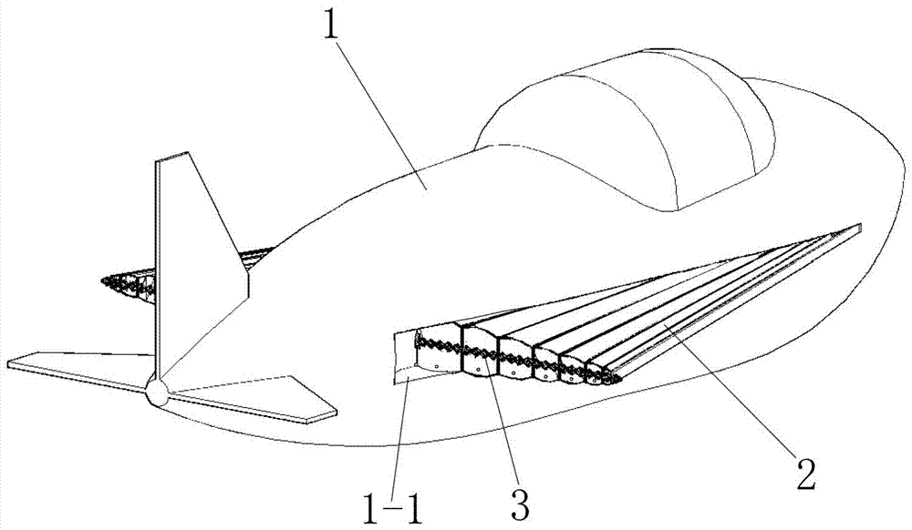
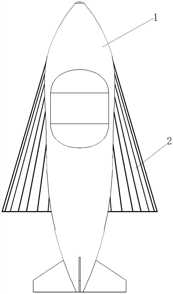
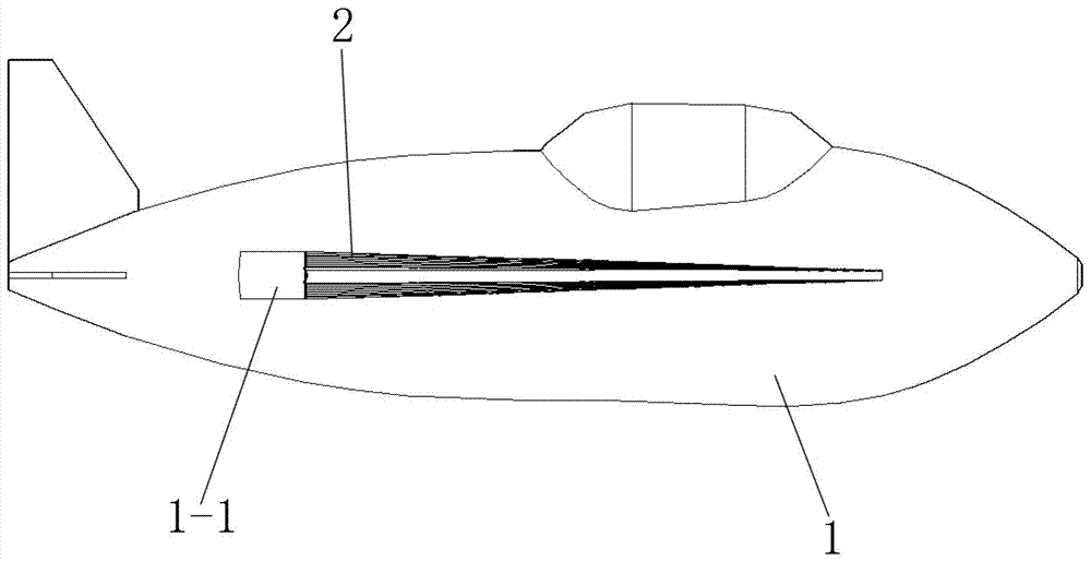
[0016] Embodiment 1, the front end of each rib 2 - 1 is rotationally connected with the fuselage 1 along the opening and closing direction through the rotating shaft 4 .

specific Embodiment 2

[0017] Embodiment 2, the rear end of each rib 2-1 is rotationally connected with the central shaft 3-1 along the opening and closing direction through a hinge 5 .

specific Embodiment 3

[0018] Embodiment 3, the root of the X-shaped telescopic mechanism 3 is rotationally connected with the fuselage 1 along the opening and closing direction through the rotating shaft 4 or the hinge 5 .

[0019] Preferably, the flexible skin 2-2 is made of aramid fiber covered with aluminum foil. Aramid fiber is also called Kevlar, which acts as a force bearing, and the aluminum foil acts as an airtight effect.


PUM


Abstract

The invention provides an inflatable hang glider unmanned aerial vehicle and belongs to the technical field of unmanned aerial vehicles. The problems that the storage and transportation space of a hang glider unmanned aerial vehicle is limited, and quick orbital transfer cannot be achieved are solved. The inflatable hang glider unmanned aerial vehicle comprises a vehicle body and inflatable side wings arranged on the two sides of the vehicle body. Each inflatable side wing is formed by connecting a plurality of ribbed plates which are arrayed in a fan shape through flexible skin in a sealed mode, the flexible skin is adhered to the ribbed plates, and air chambers are formed between every two adjacent ribbed plates through sealing of the flexible skin of the front face, the rear face, the upper face and the lower face. The width of each ribbed plate is gradually increased from the front end to the rear end, the front end widths of all the ribbed plates are the same, and the rear end widths of all the ribbed plates of each inflatable side wing are gradually increased from the outside to the inside. The ribbed plates adopt flat plates which are each of a hollow structure, air holes are formed in the side walls of the ribbed plates of the two sides of each air chamber, the front end of each ribbed plate is connected with a high-pressure air bottle and an inflating control system which are arranged in the vehicle body, and an air discharging electromagnetic valve is arranged at the rear end of each air chamber. The inflatable hang glider unmanned aerial vehicle is applied to the field of unmanned aerial vehicles.

Description

technical field [0001] The invention belongs to the technical field of unmanned aerial vehicles, and in particular relates to an inflatable gliding wing unmanned aerial vehicle. Background technique [0002] UAVs have obvious advantages such as no risk of casualties. With the rapid development of UAV technology, glider UAVs have been widely used; The space is not conducive to storage and transportation; and when the glider UAV encounters natural enemies such as birds, it cannot quickly change orbit to avoid it, and the safety hazard is relatively large; This program. Contents of the invention [0003] The purpose of the present invention is to solve the problem of limited storage and transportation space and inability to quickly change the orbit of the hang gliding UAV, and provides an inflatable hang gliding UAV. The technical solution is as follows: [0004] An inflatable hang gliding drone, which includes a fuselage and inflatable wings arranged on both sides of the f...

Claims


Application Information

Patent Timeline
Patent Type & Authority Applications(China)
IPC IPC(8): B64C3/30B64C3/56
CPCB64C3/30B64C3/56B64U10/25
Inventor 卫剑征谭惠丰甄铎
Owner HARBIN INST OF TECH
Why Eureka
Try Eureka