Connecting assembly for clothing manufacturing hanging system and clothing manufacturing hanging system

A technology for connecting components and hoisting, applied in the directions of transportation and packaging, conveyors, mechanical conveyors, etc., can solve the problems of complex structure of the entry mechanism, increasing the complexity of the control software of the hoisting system, and difficulty in ensuring that the hangers are transferred to the workstation.

Inactive Publication Date: 2017-06-27
HUIZHOU TECHZEN IOT SCI & TECH CO LTD
View PDF8 Cites 4 Cited by
  • Summary
  • Abstract
  • Description
  • Claims
  • Application Information

AI Technical Summary

Problems solved by technology

[0003] A Chinese patent (patent number: 200920318118.3) discloses a hanger system for garment making, which solves the problem that hangers are piled up on the ring rail due to the bottleneck process of the existing hanger system, which affects the smooth operation of hangers
In this hanging system, the structure of the outbound mechanism is the same as that of the inbound mechanism, and the inbound mechanism is also equipped with an inbound swing head, which is also driven by the power mechanism controlled by the central controller. The structure of the station mechanism is relatively complex, the cost is high, and its power is controlled by the central controller, which increases the complexity of the entire control software of the suspension system
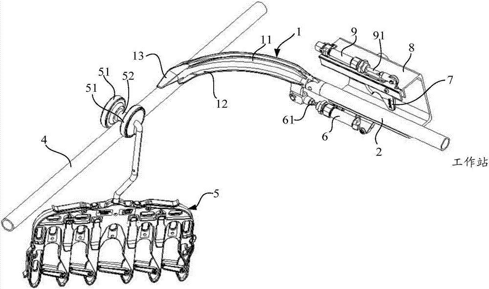
[0004] However, in the existing hanger system for clothes making, when the clothes hanger enters the workstation from the ring rail, due to the poor guiding ability of the existing swing head, the clothes hanger often swings from side to side when moving along the swing head, and may even fall off. risk, it is difficult to ensure that the hangers are stably transferred to the workstation, which is not conducive to the working stability of the garment hanging system

Method used


Image

  • Connecting assembly for clothing manufacturing hanging system and clothing manufacturing hanging system
  • Connecting assembly for clothing manufacturing hanging system and clothing manufacturing hanging system
  • Connecting assembly for clothing manufacturing hanging system and clothing manufacturing hanging system

Examples


Embodiment Construction

[0039] The following will clearly and completely describe the technical solutions in the embodiments of the present invention with reference to the accompanying drawings in the embodiments of the present invention. Obviously, the described embodiments are only part of the embodiments of the present invention, not all of them. Based on the embodiments of the present invention, all other embodiments obtained by persons of ordinary skill in the art without creative efforts fall within the protection scope of the present invention.

[0040] It should be noted that if there is a directional indication (such as up, down, left, right, front, back...) in the embodiment of the present invention, the directional indication is only used to explain the position in a certain posture (as shown in the accompanying drawing). If the specific posture changes, the directional indication will also change accordingly.

[0041] In addition, if there are descriptions involving "first", "second" and ...


PUM


Abstract

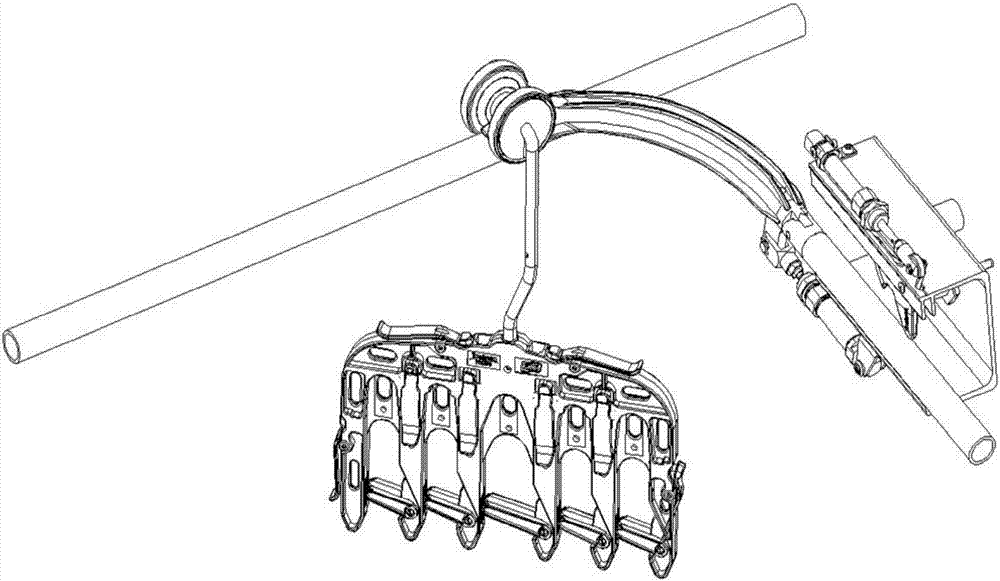
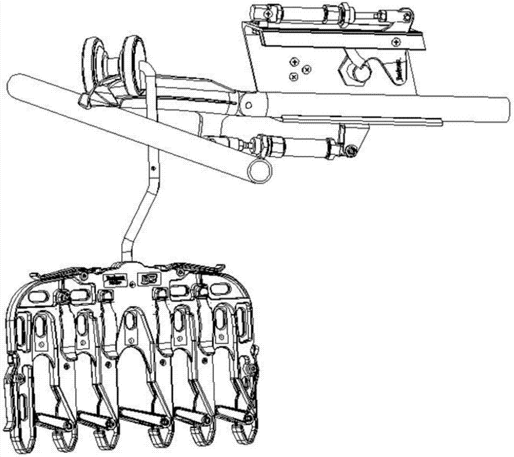
The invention discloses a connecting assembly for a clothing manufacturing hanging system and the clothing manufacturing hanging system comprising the same. The connecting assembly for the clothing manufacturing hanging system comprises a guiding connector and a guide rod, wherein one end of the guide rod is rotatably connected to the tail end of the guiding connector while the other end of the guide rod extends to a work station; the first end of the guiding connector is a free end, and the first end of the guiding connector can be selectively overlapped to a circular track; bearing beads are arranged on two opposite outer side walls of the guiding connector in a protruding manner for bearing two rollers of a clothes rack clamping a cloth material, so that the two rollers roll on the bearing beads; a guiding bead which extends along the extending direction of the guiding connector is formed on the top of the guiding connector for leaning against a roller connecting shaft between two rollers of the clothes rack clamping the cloth material; when the two rollers roll on the bearing beads, the guiding bead guides the two rollers. The connecting assembly facilitates the working stability of the clothing manufacturing hanging system.

Description

technical field [0001] The invention relates to the field of clothing hanging systems, in particular to a connecting assembly for a clothing hanging system and a clothing hanging system with the connecting assembly. Background technique [0002] The requirements for the speed of garment production make the garment hanging system widely used. There are several workstations arranged at intervals along the direction of the ring track of the garment hanging system. These workstations have an entry mechanism and an exit mechanism, which are used to guide the hangers from the ring track to the workstation and to guide the hangers from the workstation to the ring track. . Both the entry mechanism and the exit mechanism need to be equipped with a movable swing head. The swing head extends to the ring rail or separates from the ring rail under the action of the power mechanism. The action of the power mechanism is carried out by the central controller on the suspension system. cont...

Claims


Application Information

Patent Timeline
Patent Type & Authority Applications(China)
IPC IPC(8): B65G35/06
CPCB65G35/06B65G2201/0229
Inventor 李忠鹏
Owner HUIZHOU TECHZEN IOT SCI & TECH CO LTD
Why Eureka
Try Eureka